
Structure topology optimization method

A topology optimization, finite element technology, applied in design optimization/simulation, special data processing applications, instruments, etc., can solve problems such as mismatching penalty effects, inability to eliminate intermediate density cells, and discontinuous topology evolution process.

Active Publication Date: 2019-01-11
SOUTH CHINA UNIV OF TECH
View PDF5 Cites 13 Cited by
  • Summary
  • Abstract
  • Description
  • Claims
  • Application Information

AI Technical Summary

Problems solved by technology

This method realizes that the pseudo-density of the material approaches 0 or 1 through the action of the penalty factor p, thereby gradually removing the intermediate density units in the structure, but this method has two problems: 1. For the final result of the three-dimensional complex structure, there are often still a large number of intermediate densities The unit cannot be eliminated; 2. For optimization problems involving both mass and stiffness, such as structural self-weight and dynamic problems, both mass and stiffness need to be penalized at the same time, but because the physical properties of mass and stiffness are different, the same penalty factor will not be effective Matching causes convergence issues and often requires additional processing
[0007] The topology optimization method based on level set uses the zero isoline (two-dimensional problem) or zero isosurface (three-dimensional problem) of the high-dimensional scalar level set function field φ, that is, φ=0, to implicitly describe the geometry of the structure Contour or the interface of different materials, and use a specific velocity field to drive the boundary evolution of the structure, to obtain a non-zero or one discrete material distribution and a clear structural boundary, but the level set method does not exist due to the absence of intermediate densities, and the topological evolution process is discontinuous , there is often the dependence of the initial design, that is, the initial design has a greater impact on the final design

Method used


Image

  • Structure topology optimization method
  • Structure topology optimization method
  • Structure topology optimization method

Examples


Embodiment 1

[0043] like Figure 7 As shown, a method for structural topology optimization in this embodiment includes the following steps:

[0044] S1. In this embodiment, the Figure 8 Take the two-dimensional plane stress structure shown as an example to illustrate the structural topology optimization. In this structure, the left end of the initial rectangular design domain is a fixed constraint, with a length of 0.8m, a width of 0.4m, and a thickness of 0.01m. The elastic modulus of the solid material is 2.1×10 11 Pa, the modulus of elasticity of the blank material is 2.1×10 2 pa, Poisson's ratio is 0.3, and the structure is subjected to a vertical load of 100N at the midpoint of the right end. The optimization goal is to minimize the structural strain energy, and the volume equation constraint is imposed, and the volume fraction is taken as 50%.

[0045] S2, such as Figure 9-10 As shown, a four-node plane stress element is used, and through finite element modeling, the design dom...


PUM


Abstract

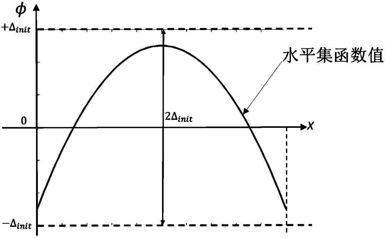
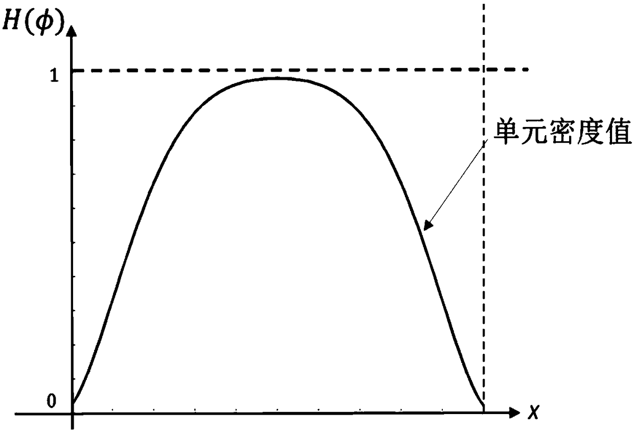
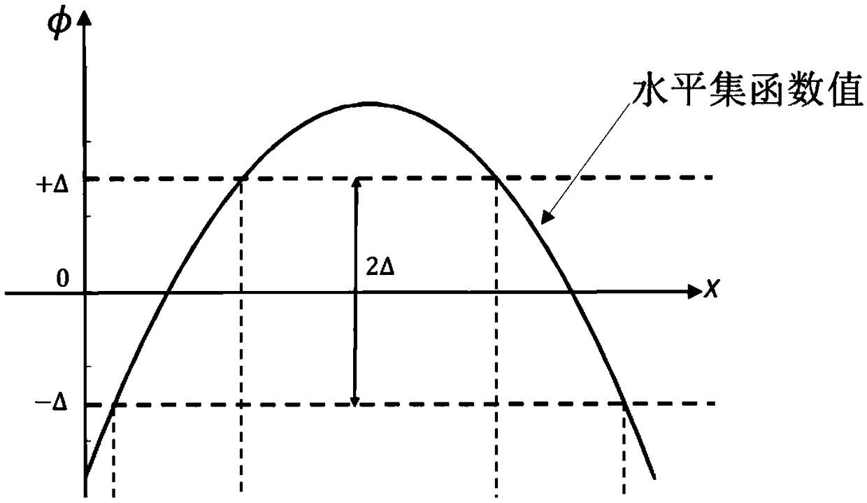
The invention discloses a structure topology optimization method, comprising the following steps: defining an initial structure and a corresponding level set function; averagely interpolating the current node level set function value phi N to obtain the initial level set function value phi of each element; introducing the concept of level set band with adjustable width and the parameter delta usedto control the intermediate density range, and processing the value phi of the level set function by the mapping function with parameter delta to get the unit density value H (phi) in the range of 0-1 to obtain the topological structure containing the intermediate density; carrying out finite element analysis of the topological structure, and updating the value phi N of the node level set function; carrying out iteration and convergence judgment to get the structure design with clear boundary; outputting optimization results. The invention can realize continuous topology evolution, solve boundary-related optimization problems, ensure physical manufacturability of optimization results, obtain reasonable structure topology, and finally obtain structure design with clear boundary expressed by zero-level set when converging.

Description

technical field [0001] The invention relates to the related technical field of structural optimization design, in particular to a structural topology optimization method based on adjustable width horizontal set bands. Background technique [0002] The variable density method (represented by the SIMP method) and the level set method based on the material interpolation model are two commonly used methods for topology optimization. [0003] The variable density method is a topology optimization method that introduces a hypothetical unit pseudo-density that can continuously take values ​​between 0 and 1 as a design variable, and then assumes that there is a functional relationship between the material physical property values ​​such as elastic modulus and pseudo-density. Among them, the SIMP model is the most commonly used model in the variable density method, and its element elastic modulus E is taken as a function of the element pseudo-density: [0004] E(ρ)=ρ p E. 0 [00...

Claims


Application Information

Patent Timeline
IPC IPC(8): G06F17/50
CPCG06F30/18G06F30/23
Inventor 魏鹏汪雯雯
Owner SOUTH CHINA UNIV OF TECH
Learn More