Panoramic real-time simulation method for power system

A real-time simulation and power system technology, applied in design optimization/simulation, electrical digital data processing, special data processing applications, etc., can solve problems that do not constitute a simulation system

Active Publication Date: 2019-01-11
STATE GRID SICHUAN ELECTRIC POWER CORP ELECTRIC POWER RES INST +2
View PDF14 Cites 12 Cited by
  • Summary
  • Abstract
  • Description
  • Claims
  • Application Information

AI Technical Summary

Problems solved by technology

More and more new technologies are introduced into the smart grid, such as simulation technology, but the existing smart grid simulation method only builds two out of the three, the primary system simulation, the secondary equipment simulation, and some real secondary equipment. The coordination and synchronous operation system among the participants does not constitute a complete simulation system

Method used


Image

  • Panoramic real-time simulation method for power system
  • Panoramic real-time simulation method for power system
  • Panoramic real-time simulation method for power system

Examples


Embodiment 1

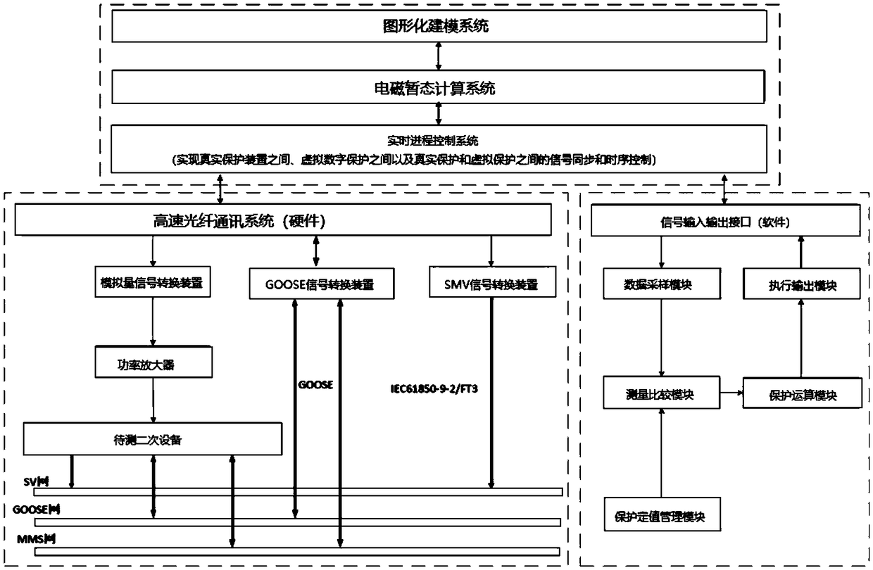
[0044] Such as figure 1 It should be noted that, in the description of the present invention, the terms "horizontal", "vertical", "upper", "lower", "front", "rear", "left", "right", "vertical The orientations or positional relationships indicated by "straight", "horizontal", "top", "bottom", "inner" and "outer" are based on the orientations or positional relationships shown in the drawings, and are only for the convenience of describing the present invention and simplifying the The description does not indicate or imply that the device or element referred to must have a particular orientation, be constructed or operate in a particular orientation, and thus should not be construed as limiting the invention.

[0045] Such as figure 1 As shown, the panoramic real-time simulation method for the power system, the following steps are performed in sequence:

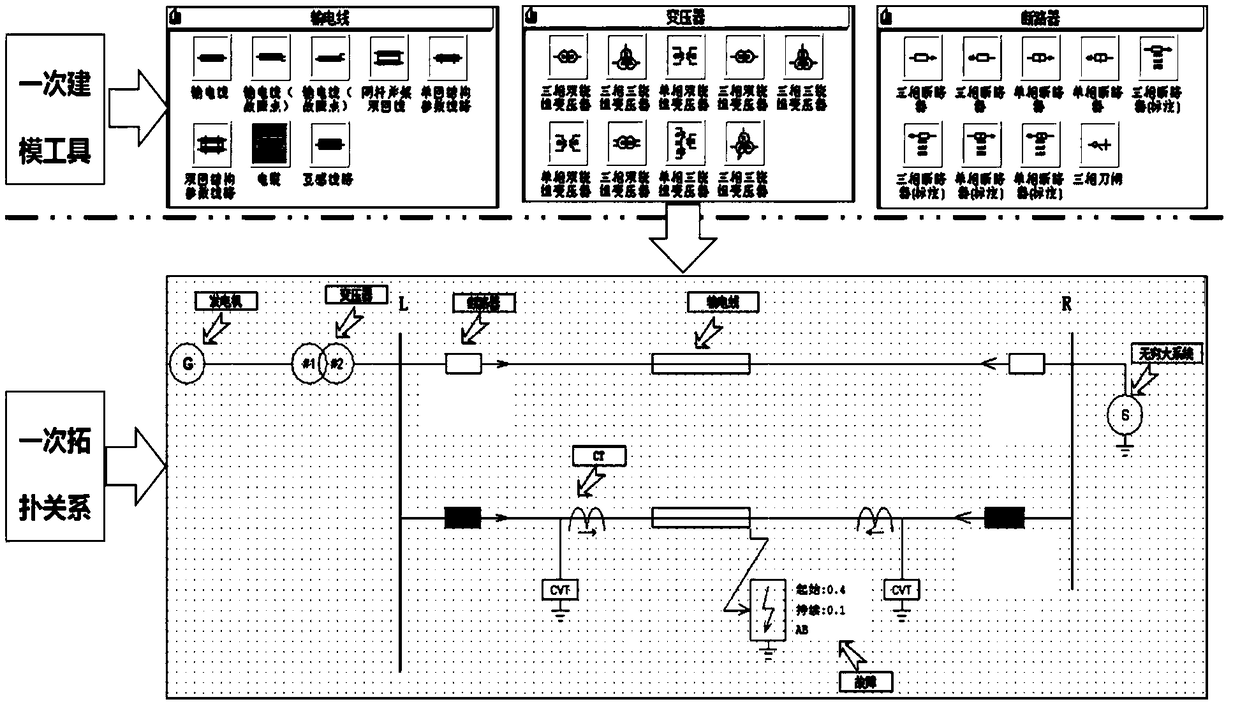
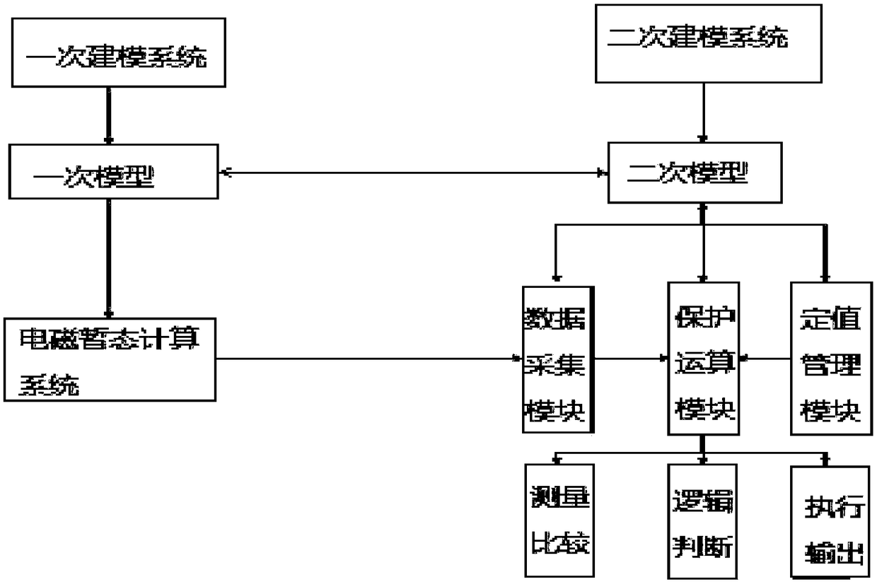
[0046] A. Construct the primary system model and secondary system model of the substation;

[0047] B. After the primary sy...

Embodiment 2

[0080] The invention provides a real-time simulation method of a smart grid, including:

[0081] Step A, building a primary system model and a secondary system model respectively;

[0082] Step B, after the primary system model calculates each step and obtains the simulation data, it is written into the real-time database, that is, the primary system model is always in the calculation state, and it will be written immediately after calculating each step In the real-time database; when the primary system model calculates any step length to obtain the simulation data and writes it into the real-time database, the analog signal conversion device and the secondary system model simultaneously read the simulation data from the real-time database. data, if the GOOSE signal conversion device and the secondary system model return information to the primary system model at the same time, the primary system model forms a new topology according to the returned information for simulation, ...


PUM


Abstract

The invention discloses a panoramic real-time simulation method for a power system, which comprises the following steps: respectively constructing a primary system model and a secondary system model of a substation; writing the simulation data of each step into the real-time database after the system model is calculated once. Once the system model has computed and written simulation data of any step size to the real-time database, the secondary system model collects the data from the real-time database; simultaneously, the primary system model transmits the simulation data to the signal converting device, and if the primary system model receives the action information sent by the secondary system model and simultaneously receives the information returned to the primary system model by thesignal converting device, the simulation is carried out according to the topology structure formed at present. The invention coordinates and synchronizes the primary system simulation, the secondary equipment simulation and part of the real secondary equipment, and has the interoperability, thereby forming a complete simulation test system, which can ensure the seamless docking of the simulation platform with the real secondary equipment and the virtual digital protection.

Description

technical field [0001] The invention relates to the technical field of power system simulation, in particular to a panoramic real-time simulation method for power systems. Background technique [0002] The smart grid is the intelligence of the grid (smart electric power), also known as "grid 2.0", which is based on an integrated, high-speed two-way communication network, through advanced sensing and measurement technology, advanced equipment technology , advanced control methods, and the application of advanced decision support system technology to achieve the goals of reliability, security, economy, efficiency, environmental friendliness, and safe use of the power grid. Power quality that meets the needs of users in the 21st century, allows access to various forms of power generation, activates the power market, and optimizes and efficiently operates assets. [0003] Smart substation technology has become the core driving force for the development of smart grids. The basic...

Claims


Application Information

Patent Timeline
Patent Type & Authority Applications(China)
IPC IPC(8): G06F17/50
CPCG06F30/20Y02E60/00
Inventor 刘明忠郑永康常晓青姜振超胡翔夏云胡明亮滕予非周文越朱鑫丁宣文韩睿刘佳钰钟翀熊俊何笠张茜
Owner STATE GRID SICHUAN ELECTRIC POWER CORP ELECTRIC POWER RES INST
Why Eureka
Try Eureka