Transmitter unit of non-contact power supply system and transmitter of non-contact power supply system

A non-contact power supply and transmitter technology, applied in electrical components, circuits, inductors, etc., can solve problems such as current imbalance, lower efficiency of transmitter, sagging and offset of transmitter cable, etc., to reduce current imbalance, Improve system emission efficiency and reduce mutual inductance

Active Publication Date: 2021-02-09
CRRC QINGDAO SIFANG CO LTD
View PDF6 Cites 0 Cited by
  • Summary
  • Abstract
  • Description
  • Claims
  • Application Information

AI Technical Summary

Problems solved by technology

[0004] Because there may be slight differences in the structural parameters of different converters and the mutual inductance between different transmitting coils, the current in different transmitting coils is unbalanced;
[0005] The external electromagnetic radiation of the transmitter of the non-contact power supply system is relatively large, which in turn causes the transmitter of the non-contact power supply system to have a relatively large adverse impact on the environment;
[0006] The feeder cable and the launch cable between the converter and the launch cable are long, and the loss is high, resulting in a decrease in the efficiency of the launch end of the entire non-contact power supply system;
[0007] The installation and fixing method of the transmitting end of the non-contact power supply system is likely to cause the transmitting cable to sag and shift, which affects the power transmission efficiency

Method used


Image

  • Transmitter unit of non-contact power supply system and transmitter of non-contact power supply system
  • Transmitter unit of non-contact power supply system and transmitter of non-contact power supply system
  • Transmitter unit of non-contact power supply system and transmitter of non-contact power supply system

Examples


Embodiment Construction

[0032] In order to understand the above-mentioned purpose, features and advantages of the present invention more clearly, the present invention will be further described in detail below in conjunction with the accompanying drawings and specific embodiments. It should be noted that, in the case of no conflict, the embodiments of the present application and the features in the embodiments can be combined with each other.

[0033] In the description of the present invention, it should be noted that the terms "center", "longitudinal", "transverse", "upper", "lower", "front", "rear", "left", "right", " The orientations or positional relationships indicated by "vertical", "horizontal", "top", "bottom", "inner" and "outer" are based on the orientations or positional relationships shown in the drawings unless otherwise specified. It is only for the convenience of describing the present invention and simplifying the description, but does not indicate or imply that the device or element...


PUM


Abstract

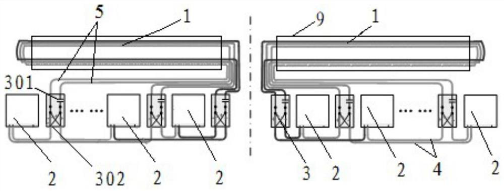
The invention relates to the technical field of non-contact power supply, and provides a non-contact power supply system transmitting end unit and a non-contact power supply system transmitting end. The transmitting end unit of the non-contact power supply system comprises a converter and a branch compensator, each converter is connected with a plurality of first output cables, and the branch compensator comprises an access end, wherein the access end is connected with the first output cables of at least two converters, and is divided into two second output cables through the branch compensator. Two second output cables of each branch compensator are connected to both ends of a transmitting coil. As that current output from different converter of the same power supply unit is couple through different transmitting coil loops, at that same time, the mutual inductance between different transmit coil loops is reduce, which can reduce the problem of current imbalance in the transmitting coil loop and improve the transmitting efficiency of the system. In addition, the non-contact power supply system transmitting end includes the above non-contact power supply system transmitting end unit.

Description

technical field [0001] The invention relates to the technical field of non-contact power supply, in particular to a transmitter unit of a non-contact power supply system and a transmitter of the non-contact power supply system. Background technique [0002] The transmitting end of the non-contact power supply system mainly includes the output of the converter to the transmitting coil, and the wireless transmission of electric energy is realized through the electromagnetic induction magnetic field coupling principle of the transmitting coil and the pickup coil. The link from the output of the converter to the transmitting coil is a very important part of the system. [0003] The problems existing in the transmitting end of the non-contact power supply system in the prior art include: [0004] Because there may be slight differences in the structural parameters of different converters and the mutual inductance between different transmitting coils, the current in different tra...

Claims


Application Information

Patent Timeline
Patent Type & Authority Patents(China)
IPC IPC(8): H02J50/10H01F38/14H01F27/28H01F27/30
CPCH01F27/28H01F27/306H01F38/14H02J50/10
Inventor 杜凯军梁建英高世萍赵冬玉冯玉明
Owner CRRC QINGDAO SIFANG CO LTD
Why Eureka
Try Eureka