
Wireless charging electric car mobile phone holder

A mobile phone bracket and wireless charging technology, which is applied to the structure of telephones, vehicle parts, transportation and packaging, etc., can solve the problems of large elastic design, affecting the appearance, and not suitable for disassembly, so as to achieve the effect of power supply

Pending Publication Date: 2019-01-11
JIANGSU ZMI ELECTRONICS TECH
View PDF4 Cites 2 Cited by
  • Summary
  • Abstract
  • Description
  • Claims
  • Application Information

AI Technical Summary

Problems solved by technology

The principle of the magnetic suction type is that one pole of the magnet is fixed on the mobile phone and the other pole is fixed on the bracket, and the mobile phone is fixed on the bracket through the attraction of the positive and negative poles of the magnet. However, the existing method is to pass one pole of the magnet through The way of pasting is fixed on the mobile phone, which is not suitable for disassembly and affects the appearance
The principle of the telescopic type is to use the elastic force of the spring to make the left and right clamping arms clamp the mobile phone in the middle. The disadvantage of this method is that in order to prevent the mobile phone from falling, the elastic force is designed to be relatively large, and it is not easy to separate the clamping arm from the mobile phone with one hand.
The principle of the gravity type is to set up three linked clamping arms on the left, right and bottom. The lower clamping arm is pressed down by the weight of the mobile phone and the left and right clamping arms are driven to clamp the mobile phone. Unable to continue to apply pressure to the lower clamp arm, the clamping force of the left and right clamp arms becomes smaller, and the mobile phone falls off the bracket

Method used


Image

  • Wireless charging electric car mobile phone holder
  • Wireless charging electric car mobile phone holder
  • Wireless charging electric car mobile phone holder

Examples


Embodiment Construction

[0021] Up and down described in this specific embodiment. Left and right are upper, lower, left and right in the corresponding drawings.

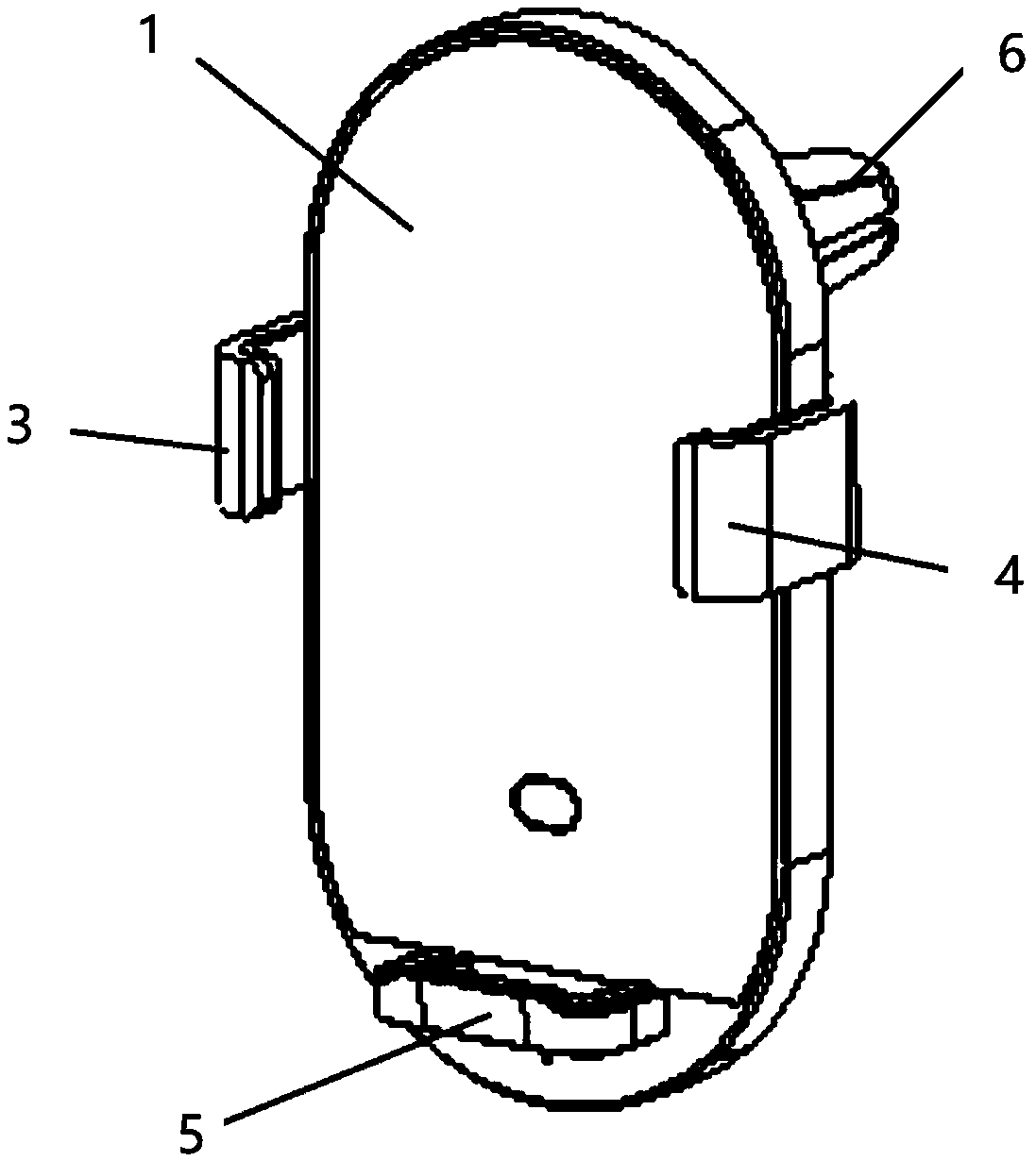
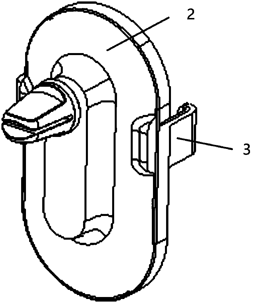
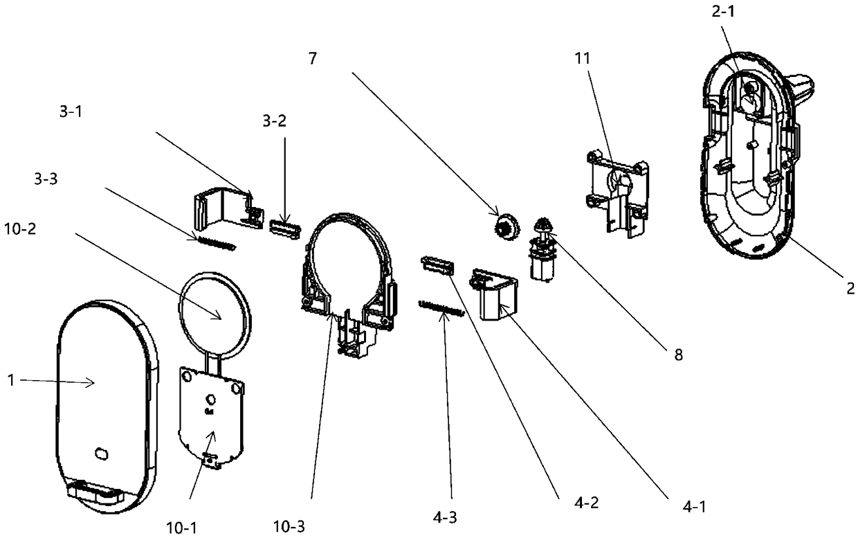
[0022] combine figure 1 , figure 2 , a mobile phone holder for a wireless charging electric vehicle, comprising a front case 1, a rear case 2, a left clamp arm assembly 3, a right clamp arm assembly 4, a lower bar 5, and a clamp 6. combine figure 2 , Figure 9 , the bracket also includes a drive unit, a main board 10-1, a charging coil 10-2, a sensor 12-1, and a touch button 12-2.

[0023] The front shell 1 and the rear shell 2 are in the shape of a waist hole, and the edges of the two are connected to form a bracket body, and a cavity is arranged inside the bracket body. The lower bar 5 is fixed on the lower part of the front case 1, and the lower bar 5 protrudes from the end face of the front case 1, and is a platform for placing the lower end of the mobile phone. The clamp 6 is arranged on the rear shell 2 through the universal b...


PUM


Abstract

The present invention provides a wireless charging electric car mobile phone holder. The wireless charging electric car mobile phone holder comprises a front casing, a rear casing, a left clamping arm, a right clamping arm, a lower blocking strip, a clamp, a drive unit, a mainboard, a charging coil, an inductor and a touch key; the front casing is connected with the rear casing to form a holder body, the clamp is arranged on the rear casing, the lower blocking strip is arranged at the lower portion of the front casing, the tail ends of the left clamping arm and the right clamping arm stretch into the holder body, the holding sections of the left clamping arm and the right clamping arm are configured to clamp the mobile phone, the mainboard is arranged in the holder body, the drive unit isarranged in the holder body and is electrically connected with the mainboard, the drive unit is cooperated with the tail ends of the left clamping arm and the right clamping arm, the left clamping armand the right clamping arm perform motion in the opposite directions under the drive of the drive unit, the charging coil is arranged in the holder body and is electrically connected with the mainboard, the inductor is arranged on the end face of the front casing and is in signal connection with the mainboard, the touch key is arranged on the upper blocking strip and is in signal connection withthe mainboard, and the holder body is provided with a charging port electrically connected with the mainboard.

Description

technical field [0001] The invention relates to a vehicle-mounted mobile phone holder, in particular to a wireless charging electric vehicle-mounted mobile phone holder. Background technique [0002] With the development of social environment, mobile phones have become a necessity of our life. Now that private cars are becoming more and more popular, the demand for car mobile phone holders is also increasing. At present, there are many car mobile phone holders on the market, and magnetic suction type, telescopic type or gravity type are generally used. The principle of the magnetic suction type is that one pole of the magnet is fixed on the mobile phone and the other pole is fixed on the bracket, and the mobile phone is fixed on the bracket through the attraction of the positive and negative poles of the magnet. However, the existing method is to pass one pole of the magnet through The way of pasting is fixed on the mobile phone, which is not suitable for disassembly and a...

Claims


Application Information

Patent Timeline
Patent Type & Authority Applications(China)
IPC IPC(8): H04M1/04B60R11/02
CPCH04M1/04B60R11/0241B60R2011/0071
Inventor 张峰李辉
Owner JIANGSU ZMI ELECTRONICS TECH
Learn More