Tunnel type wood veneer drying production line

A wood veneer and tunnel-type technology, applied in the direction of veneer drying, drying, drying machine, etc., can solve the problems of different drying efficiency and drying effect of hot air drying devices, and achieve ingenious structure setting and uniform heating , the effect of not easy to deform

Pending Publication Date: 2022-05-13
广西青松木业有限公司
View PDF16 Cites 2 Cited by
  • Summary
  • Abstract
  • Description
  • Claims
  • Application Information

AI Technical Summary

Problems solved by technology

Through practical application research, it is found that the drying efficiency and drying effect of hot air drying devices with different structures are different, and the current tunnel drying device cannot realize the vertical conveying of wood veneers for flow drying

Method used


Image

  • Tunnel type wood veneer drying production line
  • Tunnel type wood veneer drying production line
  • Tunnel type wood veneer drying production line

Examples


Embodiment 1

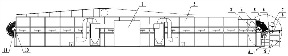
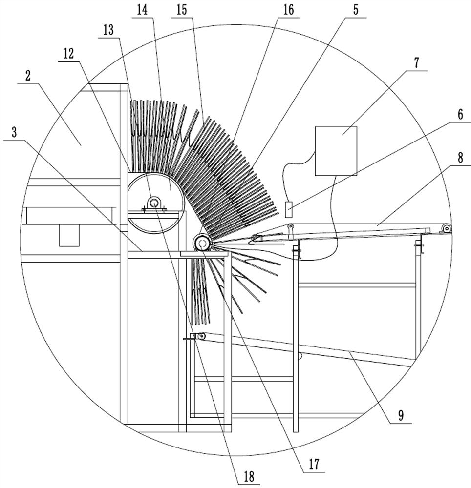
[0024]A tunnel-type wood veneer drying production line, including a hot blast stove 1, a tunnel-type drying room body 2 and a chain conveying device 4, the hot-blast stove 1 is connected to the tunnel-type drying room body 2 through an air duct to form a tunnel The drying room 2 provides hot air, and the chain conveying device 4 is installed through the tunnel drying room 2 for transporting wood veneers. The chain conveying device 4 includes a frame 3, and the two sides of the frame 3 A No. I driven shaft 18 and a No. II driven shaft 11 are respectively installed in parallel through bearings with seat 13, and a No. I driven sprocket 14 is respectively installed on both ends of the No. I driven shaft 18, and No. II driven shaft A No. Ⅱ driven sprocket 10 is installed at both ends of the shaft 11, and a driving shaft 17 is installed in parallel on the front upper or lower part of the No. 1 driven shaft 18 through a bearing 13, and the two ends of the driving shaft 17 are respecti...

Embodiment 2

[0026] A tunnel-type wood veneer drying production line, including a hot blast stove 1, a tunnel-type drying room body 2 and a chain conveying device 4, the hot-blast stove 1 is connected to the tunnel-type drying room body 2 through an air duct to form a tunnel The drying room 2 provides hot air, and the chain conveying device 4 is installed through the tunnel drying room 2 for transporting wood veneers. The chain conveying device 4 includes a frame 3, and the two sides of the frame 3 A No. I driven shaft 18 and a No. II driven shaft 11 are respectively installed in parallel through bearings with seat 13, and a No. I driven sprocket 14 is respectively installed on both ends of the No. I driven shaft 18, and No. II driven shaft A No. Ⅱ driven sprocket 10 is installed at both ends of the shaft 11, and a driving shaft 17 is installed in parallel on the front upper or lower part of the No. 1 driven shaft 18 through a bearing 13, and the two ends of the driving shaft 17 are respect...


PUM


Abstract

A tunnel type wood veneer drying production line comprises a hot blast stove, a tunnel type drying room body and a chain conveying device, the hot blast stove provides hot air, the chain conveying device conveys wood veneers, the chain conveying device comprises a machine frame, and a first driven shaft and a second driven shaft are installed at the two ends of the machine frame respectively. A first driven chain wheel and a second driven chain wheel are installed at the two ends of the first driven shaft and the two ends of the second driven shaft respectively, a driving shaft with small driving chain wheels at the two ends is installed on the upper portion or the lower portion in front of the first driven shaft, and the small driving chain wheels, the first driven chain wheels and the second driven chain wheels at the corresponding ends are connected in a closed-loop mode through plate type conveying chains. And an automatic clamp for clamping a wood veneer is arranged between chain plates corresponding to each section of chain of the two plate type conveying chains. According to the drying production line, the wood veneers can be vertically conveyed into the tunnel drying room to be dried, the plate type conveying chain circularly rotates in the tunnel drying room, discharging is conducted when the plate type conveying chain rotates to the inlet end, and continuous flow drying operation is achieved.

Description

technical field [0001] The invention relates to the technical field of wood drying equipment, in particular to a tunnel-type wood veneer drying production line. Background technique [0002] Wooden veneer is to cut the trees with economic use value into a certain length and then use mechanical equipment (with or without card veneer rotary cutter) to cut them into a specified thickness along the round surface of the trunk. According to national standards, it is generally 0.5~ Ribbon sheets of various specifications between 3.2mm. The wood veneer after rotary cutting is widely used in construction, industry, agriculture, military and many other fields as the basic material of man-made composite board. For a long time, due to its unique physical properties and economic cost constraints, the drying of rotary cutting boards at home and abroad has been using natural drying methods. Due to the limitations of natural weather conditions, venues, manpower and other factors, natural d...

Claims


Application Information

Patent Timeline
Patent Type & Authority Applications(China)
IPC IPC(8): F26B15/12F26B25/00
CPCF26B15/12F26B25/003F26B2210/14
Inventor 陈明锦杨彬罗茜
Owner 广西青松木业有限公司
Why Eureka
Try Eureka