Free piston device and method for operating a free piston device

A piston and free technology, applied in the direction of free piston engine, internal combustion piston engine, reciprocating piston engine, etc., can solve the problems of unsuitable external source ignition operation, etc., and achieve the effect of increased turbulent flame speed, fast conversion and low emission

Active Publication Date: 2019-01-11
DEUTSCHES ZENTRUM FÜR LUFTUND RAUMFAHRT EV
View PDF5 Cites 2 Cited by
  • Summary
  • Abstract
  • Description
  • Claims
  • Application Information

AI Technical Summary

Problems solved by technology

However, this airflow proved to be less s

Method used


Image

  • Free piston device and method for operating a free piston device
  • Free piston device and method for operating a free piston device
  • Free piston device and method for operating a free piston device

Examples


Embodiment Construction

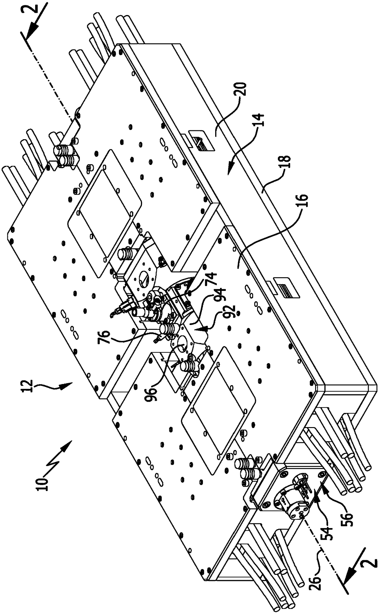
[0054] The drawing shows a preferred embodiment of the free-piston device according to the invention, referenced 10 , which in particular forms a free-piston motor 12 .

[0055] The free piston device 10 comprises an outer housing 14 , which here is cuboid and designed as a flat shell. The housing 14 defines a receiving space 22 between the top wall 16 , the bottom wall 18 and the side walls 20 .

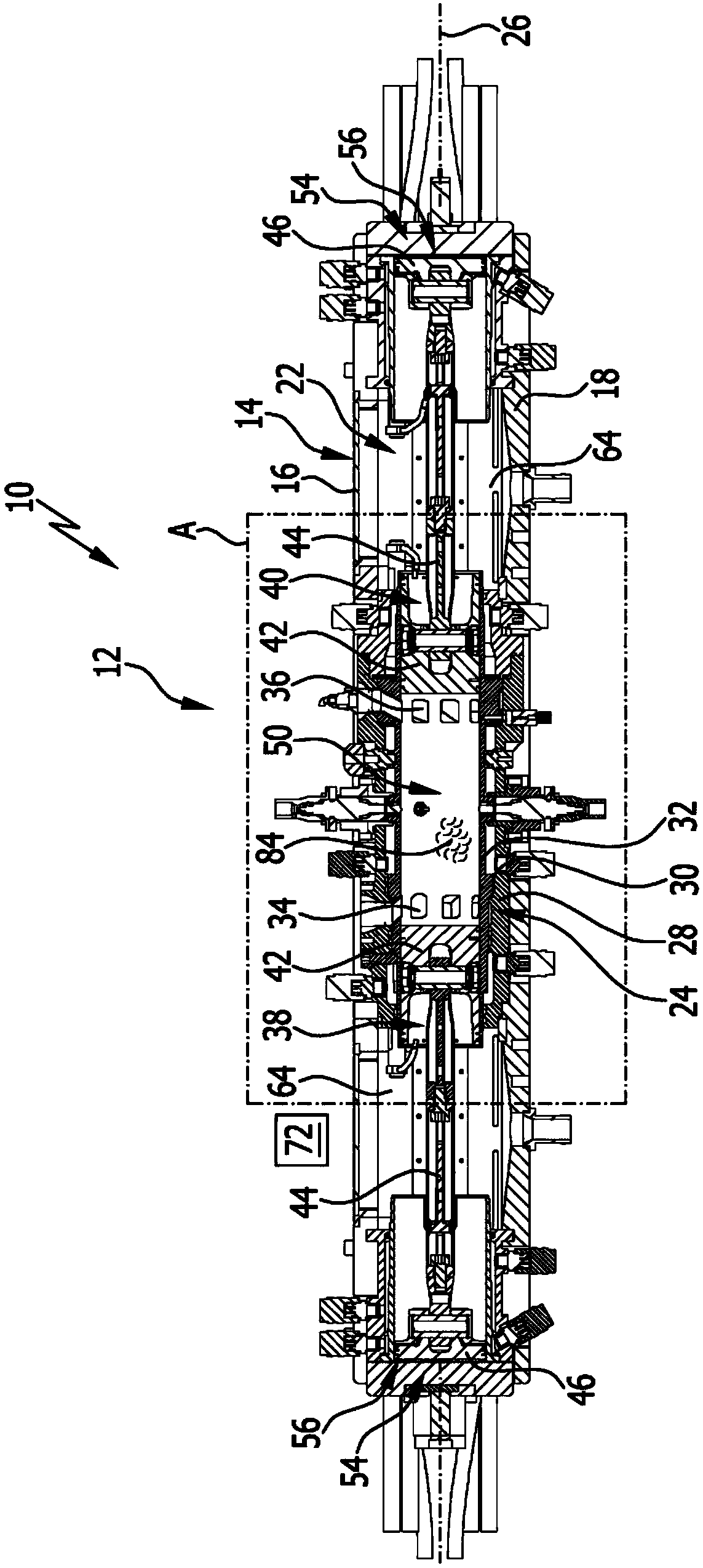
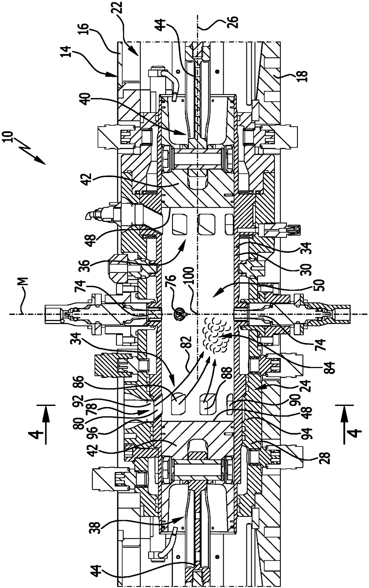
[0056] A piston chamber 24 is arranged in the housing 14 . The piston cavity 24 extends longitudinally and defines an axis 26 of the free piston device 10 . The piston chamber 24 has a housing 28 divided into separate parts, which is approximately in the shape of a hollow cylinder. A piston bushing 30 of the piston chamber 24 is arranged in the housing 28 . Piston bushing 30 becomes hollow cylinder shape substantially, and inserts the middle section of housing 28 ( Figures 2 to 4 ).

[0057] An opening is provided on the inner wall 32 of the piston bushing 30 and thus forms th...


PUM


Abstract

The invention relates to a free piston device and to a method for operating same, comprising a piston (42) which is arranged such that it can move back and forth along an axis (26). The piston receptacle (24) comprises or forms a combustion chamber (50) which is delimited by a wall (32) and which has at least one inlet opening (34, 80, 86, 88, 90) for supplying fresh gas and, at an axial distancetherefrom, at least one outlet opening (36) for discharging exhaust gas. The free piston device (10) comprises an inflow device (78) for fresh gas, said inflow device having the at least one inlet opening (34, 80, 86, 88, 90) and being designed such that fresh gas flowing into the combustion chamber (50) is directed towards an inflow region (84), which is axially offset relative to the at least one inlet opening (34, 80, 86, 88, 90) in the direction of the at least one outlet opening (36), in the combustion chamber (50), said inflow region being arranged off-center relative to the axis (26).

Description

technical field [0001] The invention relates to a free piston device comprising a piston chamber in which is arranged at least one piston assembly having a piston capable of reciprocating movement along an axis, wherein the piston chamber includes or forms a combustion chamber defined by an inner wall On the inner wall of the chamber, at least one air inlet for supplying fresh gas and at least one air outlet for exhausting exhaust gas are arranged at intervals in the axial direction. [0002] Furthermore, the invention relates to a method for operating a free piston device of this type. Background technique [0003] In such free-piston units, which typically operate in two-stroke mode, the piston assembly oscillates back and forth in the piston chamber. During the combustion of the gas-fuel mixture in the combustion chamber, the piston moves from top dead center to bottom dead center. When at bottom dead center, at least one intake port and at least one exhaust port are op...

Claims


Application Information

Patent Timeline
IPC IPC(8): F02B31/00F02B71/00F01B11/00F02B63/04
CPCF02B31/00F02B71/00F01B11/00F02B63/041Y02T10/12F01B7/02F01B11/007F01B11/02F01P3/02F02B71/04F02B75/282F02B2075/025
Inventor S·施奈德尔
Owner DEUTSCHES ZENTRUM FÜR LUFTUND RAUMFAHRT EV
Why Eureka
Try Eureka