Particle combustion furnace

A combustion furnace and particle technology, applied in the direction of combustion equipment, combustion methods, solid fuel combustion, etc., can solve the problems of inconvenient use, inconvenience, difficulty in maintaining the primer and extinguishing, and achieve the effect of avoiding backfire and extinguishing

Active Publication Date: 2021-05-28
深圳市艾斯默克科技有限公司
View PDF8 Cites 2 Cited by
  • Summary
  • Abstract
  • Description
  • Claims
  • Application Information

AI Technical Summary

Problems solved by technology

[0002] Existing pellet burning stoves, such as barbecue grills, use a burner that is basically a closed bottom structure. After each use, the ashes after the pellet fuel is burned are cleaned by a vacuum cleaner, which is very inconvenient and the user experience is not good. good
Another example is the heating furnace, which is generally equipped with a layer of grate for ash falling, but the pellet fuel of biomass is generally an extruded cylindrical structure with a diameter of about 6mm and a length of 2 to 6cm, and the pellet fuel produced by combustion If there is no external force, the ash will remain cylindrical, so it is difficult to fall directly, resulting in poor ash fall efficiency and effect. After burning for a long time, it still needs other components to assist in breaking up the ash to clean it. Not only the structure is relatively Complicated, expensive to produce, and requires user involvement, making it inconvenient to use
In addition, the burner may flash back from the feed port in a high-fire state, and it is easy to have a primer that is difficult to maintain and go out in a low-fire state.

Method used


Image

  • Particle combustion furnace
  • Particle combustion furnace
  • Particle combustion furnace

Examples


Embodiment 1

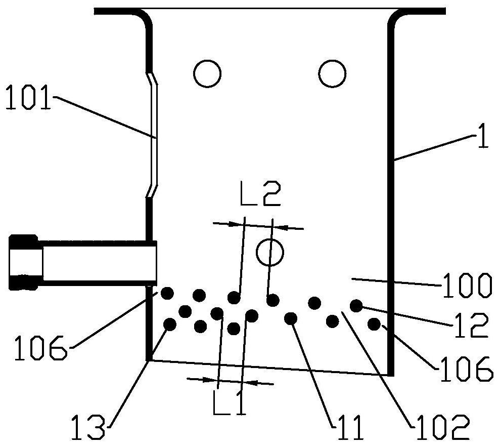
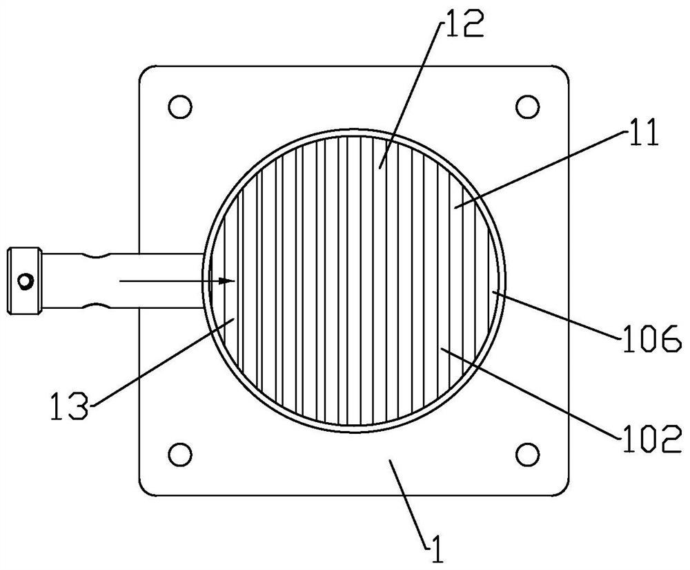
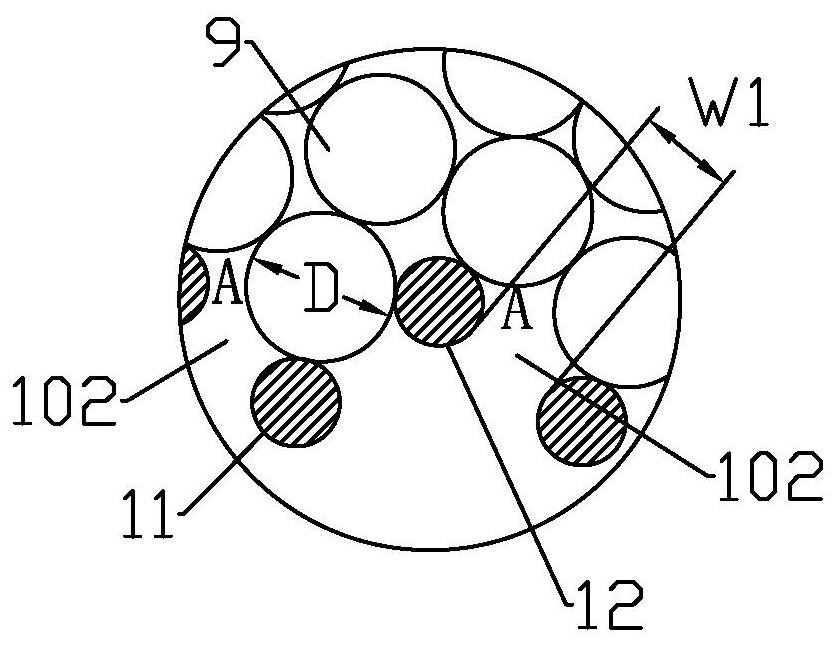
[0025] The invention provides a particle combustion furnace, comprising a furnace body, the furnace body is provided with a burner 1, such as Figure 1 to Figure 3 As shown, the top of the burner 1 is open, the side wall of the burner 1 is provided with a feed port 101, the bottom surface of the burner 1 is provided with a through-hole for air intake and ash fall, and a support particle fuel 9 is provided above the through-hole. The fire grate, the auxiliary support body 13 is provided under the fire grate, the auxiliary support body is higher than the through opening, the auxiliary support body 13 is located on the side below the feed port 101 and the setting range does not exceed 1 / 2 of the area covered by the fire grate, The 1 / 2 here is just an approximate number, so as not to affect the normal ash fall and air intake. The ash falling through the through opening avoids the accumulation of ashes after the combustion of the particulate fuel 9 at the bottom of the burner 1. Un...

Embodiment 2

[0032]In addition to designing the burner 1 into a cylindrical shape, it can also be Figure 4 and Figure 5 The shown design is a hollow prism. Specifically, the burner 1 includes a first side wall 1001 with a feed inlet 101 and a second side wall 1002 and a third side wall 1003 located on both sides of the first side wall 1001. The side wall 1002 and the third side wall 1003 expand to both sides along the feed direction of the feed port to form a figure-eight shape, and the auxiliary support 13 is connected to the bottom of the second side wall 1002 and the third side wall 1003 . The second side wall 1002 and the third side wall 1003 form a figure-eight shape, which can prevent particulate fuel from accumulating below the feed port 101 and is also beneficial to prevent tempering at the feed port 101 .

[0033] In this embodiment, the first layer of support 11 and the second layer of support 12 are parallel to the feeding direction of the feed port 101, and the auxiliary sup...

Embodiment 3

[0036] Such as Figure 6 and Figure 7 See, the body of furnace 2 is provided with a mounting frame 21 for installing the burner 1, and the mounting frame 21 is a cuboid structure. Refer to Figure 4 and Figure 5 , the burner 1 includes a first side wall 1001, a second side wall 1002, a third side wall 1003, a fourth side wall 1004, a fifth side wall 1005 and a sixth side wall 1006, and the feed inlet is located on the first side wall 1001, the second side wall 1002 and the third side wall 1003 are located on both sides of the first side wall 1001, the fourth side wall 1004 is connected to the second side wall 1002, the fifth side wall 1005 is connected to the third side wall 1003, and the sixth The side walls 1006 are respectively connected to the fourth side wall 1004 and the fifth side wall 1005 , and the fourth side wall 1004 , the fifth side wall 1005 and the sixth side wall 1006 are respectively parallel to the opposite side walls of the installation frame 21 . It ca...


PUM


Abstract

The invention discloses a particle combustion furnace, and belongs to the field of combustion equipment. The problems that in the prior art, the situation of backfire possibly happens to a combustor from a feed port in a big fire state, and the situation that primers are hard to maintain and are extinguished is prone to happening in a small fire state are solved. According to the main technical scheme for solving the problems, a combustor is arranged in a furnace body, the top end of the combustor is open, a feeding port is formed in the side wall of the combustor, a through port used for air inlet and ash falling is formed in the bottom face of the combustor, a fire grate used for supporting particle fuel is arranged above the through port, an auxiliary supporting body used for maintaining primers is arranged below the fire grate, the auxiliary supporting body is higher than the through port, the auxiliary supporting body is located on one side below the feeding port, and the set range does not exceed 1 / 2 of the area covered by the fire grate. The particle combustion furnace is mainly used for achieving the aims that backfire is not prone to happening to the feeding port in a big fire state, and extinguishing can be avoided in a small fire state.

Description

technical field [0001] The invention relates to the field of combustion equipment, in particular to a particle combustion furnace. Background technique [0002] Existing pellet burning stoves, such as barbecue grills, use a burner that is basically a closed bottom structure. After each use, the ashes after the pellet fuel is burned are cleaned by a vacuum cleaner, which is very inconvenient and the user experience is not good. good. Another example is the heating furnace, which is generally equipped with a layer of grate for ash falling, but the pellet fuel of biomass is generally an extruded cylindrical structure with a diameter of about 6mm and a length of 2 to 6cm, and the pellet fuel produced by combustion If there is no external force, the ash will remain cylindrical, so it is difficult to fall directly, resulting in poor ash fall efficiency and effect. After burning for a long time, it still needs other components to assist in breaking up the ash to clean it. Not only...

Claims


Application Information

Patent Timeline
Patent Type & Authority Applications(China)
IPC IPC(8): F23B40/00F23J1/02F23L1/00
CPCF23B40/00F23J1/02F23L1/00F23B50/12A47J37/07F24B1/024F24B1/26F24B5/023F24B13/008F24B13/006
Inventor 郑颖
Owner 深圳市艾斯默克科技有限公司
Why Eureka
Try Eureka