Eureka AIR delivers breakthrough ideas for toughest innovation challenges, trusted by R&D personnel around the world.

Wall grooving machine for water and electricity equipment installation

A technology of equipment installation and slotting machine, which is applied in the direction of stone processing equipment, stone processing tools, work accessories, etc., can solve the problems of the operator falling down the slotting speed and the height of the slotting machine can not be adjusted, etc., to achieve simple structure, Depth-controllable, easy-to-use effects

Inactive Publication Date: 2019-01-15
邵帅
View PDF1 Cites 14 Cited by
  • Summary
  • Abstract
  • Description
  • Claims
  • Application Information

AI Technical Summary

Problems solved by technology

[0003] However, the above-mentioned wall slotting machine needs to be carried by hand for slotting, and the slotting machine cannot adjust the height. When slotting a high wall, the operator needs to stand at a high place and hold the slotting machine in hand. It is easy to fall from a high place and the slotting speed is slow, so we propose a wall slotting machine for hydroelectric equipment installation to solve the above problems

Method used


Image

  • Wall grooving machine for water and electricity equipment installation
  • Wall grooving machine for water and electricity equipment installation
  • Wall grooving machine for water and electricity equipment installation

Examples


Embodiment

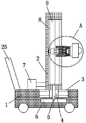
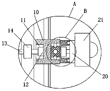
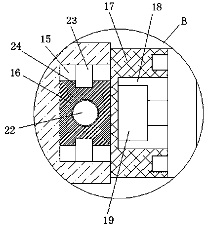
[0025] refer to Figure 1-5 In this embodiment, a wall slotting machine for installing hydropower equipment is proposed, including a base 1, a chute 3 is provided on the top of the base 1, a slider 4 is slidably installed in the chute 3, and the top of the slider 4 A riser 2 is fixedly installed, the bottom of the riser 2 is in contact with the top of the base 1, a moving groove 8 is provided on one side of the riser 2, and the same rack 9 is fixedly installed on the top inner wall and the bottom inner wall of the moving groove 8 A horizontal plate 10 is slidably installed in the moving groove 8, and a first mounting groove 11 is provided on one side of the horizontal plate 10, and a first rotating motor 12 is fixedly installed on the inner wall of one side of the first mounting groove 11, and the first rotating motor 12 A rotating rod 13 is fixedly installed on the output shaft of the rotating rod 13, and a gear 14 is fixed on the outer side of the rotating rod 13. The gear 1...


PUM


Abstract

The invention discloses a wall grooving machine for water and electricity equipment installation. The wall grooving machine comprises a base, the top of the base is provided with a sliding slot, a sliding block is slidingly installed in the sliding slot, and a vertical plate is fixedly installed on the top of the sliding block. The bottom of the vertical plate is in contact with the top of the base, one side of the vertical plate is provided with a moving groove, the top inner wall and the bottom inner wall of the moving groove are fixedly equipped with the same rack, and a horizontal plate isslidingly installed in the moving groove. One side of the horizontal plate is provided with a first mounting slot, and the inner wall of one side of the first mounting slot is fixedly equipped with afirst rotating motor whose output shaft is fixedly equipped with a rotating rod. According to the wall grooving machine, the adjustment of the position of a grooving machine body is facilitated, at the same time, the rotation of the grooving machine body is facilitated, the lateral and longitudinal grooving at different positions of the wall is facilitated, at the same time, the movement distanceof the vertical plate can be accurately adjusted, so the depth of grooving of a grooving wheel is controllable, the structure is simple, and the wall grooving machine is convenient to use.

Description

technical field [0001] The invention relates to the technical field of air control valves, in particular to a wall slotting machine used for installing hydroelectric equipment. Background technique [0002] Hydropower is one of the key points of home decoration. The hydropower installer project includes the following steps: slotting, installation, inspection, waterproofing, circuit slotting, and circuit wiring; slotting in home decoration is mainly to slot the wall. Pipe lines provide installation channels. Grooving is the first step and one of the key steps in hydropower installation engineering. Grooving requires a slotting machine. After retrieval, the patent document with application number: 201410590955.7 discloses a wall slotting machine, including The base, the motor, the transmission and the slotting wheel, the base is fixedly connected to the motor, the motor is connected to the transmission through the motor shaft, the transmission is connected to the slotting whee...

Claims


Application Information

Patent Timeline
IPC IPC(8): B28D1/04B28D1/24B28D7/00
CPCB28D1/045B28D1/24B28D7/00B28D7/005
Inventor 邵帅
Owner 邵帅
Why Eureka
Eureka Blog
Learn More