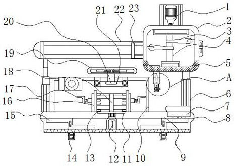
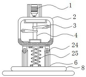
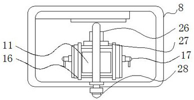
A mechanical mold with positioning and temperature control function that can push the mold in multiple directions

A functional and die-pulling technology, applied in the field of multi-directional die-pushing mechanical die, which can solve the problems of user inconvenience, push out, and inability to control the temperature of mechanical die, and achieve the effect of not easy to shake, avoid spillage, and facilitate movement.

Active Publication Date: 2021-05-07
威海晓明机械加工有限公司
View PDF9 Cites 0 Cited by
  • Summary
  • Abstract
  • Description
  • Claims
  • Application Information

AI Technical Summary

Problems solved by technology

[0003] An auxiliary frame disclosed in the Chinese invention patent application publication CN206825985U, the mechanical mold with cooling function is provided with a shaping mold, the inside of the shaping mold is a hollow structure, dry ice is placed in this hollow structure, and absorbed by the vaporization of thousands of ice The heat of the mold is used to cool the mold and absorb heat to ensure that the mold can be cooled quickly. The sprayer and the fan are at the same height. The sprayer is connected to the base of the water tank. The sprayer sprays water out, and the fan blows the moisture mixed in the air to the surface of the mold. , the mold is cooled by these moisture, the cooling coil in the cooler is connected with the base of the water tank, so that the water outlet of the cooling coil and the base of the water tank form a circulation structure, and the water in the cooling coil can be sprayed out by the sprayer to ensure Work efficiency, save energy, but it can't conveniently control the temperature of the mechanical mold, which brings inconvenience to the user, and can't push the mold out of the mold box from the inside of the mold box after forming. For this reason, We propose a mechanical mold with positioning and temperature control functions that can push molds in multiple directions

Method used


Image

  • A mechanical mold with positioning and temperature control function that can push the mold in multiple directions
  • A mechanical mold with positioning and temperature control function that can push the mold in multiple directions
  • A mechanical mold with positioning and temperature control function that can push the mold in multiple directions

Examples


Embodiment Construction

[0026] The following will clearly and completely describe the technical solutions in the embodiments of the present invention with reference to the accompanying drawings in the embodiments of the present invention. Obviously, the described embodiments are only some, not all, embodiments of the present invention.

[0027] In the description of the present invention, unless otherwise stated, the meaning of "plurality" is two or more; the terms "upper", "lower", "left", "right", "inner", "outer" , "front end", "rear end", "head", "tail", etc. indicate the orientation or positional relationship based on the orientation or positional relationship shown in the drawings, and are only for the convenience of describing the present invention and simplifying the description, rather than Nothing indicating or implying that a referenced device or element must have a particular orientation, be constructed, and operate in a particular orientation should therefore not be construed as limiting ...


PUM


Abstract

The invention relates to a mechanical mold with positioning and temperature control functions and multi-directional mold pushing, which includes a rotating motor and a slider group. A rotating shaft is installed, the outer wall outside the rotating shaft is connected with paddles, the inner wall inside the bottom of the storage frame main body is equipped with a heating wire, and the outer wall outside the heating wire is bonded to the bottom of the inner inner wall of the storage frame main body connected, the left end of the outer wall of the main body of the storage frame is provided with a fixing plate. The beneficial effect of the present invention is: when the interior of the mold is injected, the main body of the storage frame can be moved left and right through the interaction between the slider group and the fixed plate, which is convenient for the main body of the storage frame to inject the mold, and avoids When the mold is injected, it is inconvenient due to the angle problem, and the slider group is provided with two groups that can slide with the upper and lower ends of the inner wall of the fixed plate, which can be more stable.

Description

technical field [0001] The invention relates to the technical field of mechanical mold devices, in particular to a mechanical mold with the function of positioning and temperature control that can push molds in multiple directions. Background technique [0002] Mold, various molds and tools used in industrial production for injection molding, blow molding, extrusion, die-casting or forging forming, smelting, stamping and other methods to obtain the required products. In short, molds are tools used to shape objects. This tool is composed of various parts, and different molds are composed of different parts. There are various types and materials of molds, such as a mechanical mold. The appearance of molds has played a major role in industry. [0003] An auxiliary frame disclosed in the Chinese invention patent application publication CN206825985U, the mechanical mold with cooling function is provided with a shaping mold, the inside of the shaping mold is a hollow structure, dr...

Claims


Application Information

Patent Timeline
Patent Type & Authority Patents(China)
IPC IPC(8): B29C45/26B29C45/40B29C45/46B29C45/73B29C45/33
CPCB29C45/26B29C45/2608B29C45/33B29C45/40B29C45/46B29C45/73B29C45/7337
Inventor 方楚持
Owner 威海晓明机械加工有限公司
Why Eureka
Try Eureka