
Forming cylinder device for 3D printer

A technology of 3D printers and molding cylinders, which is applied in manufacturing auxiliary devices, processing data acquisition/processing, additive processing, etc. It can solve problems affecting the structure and appearance of equipment, inconvenient operation, and low equipment utilization, so as to improve utilization High efficiency and production efficiency, shorten the time for cleaning powder, and reduce the effect of powder pollution

Inactive Publication Date: 2019-01-15
GUANGZHOU LEIJIA TECH CO LTD
View PDF6 Cites 6 Cited by
  • Summary
  • Abstract
  • Description
  • Claims
  • Application Information

AI Technical Summary

Problems solved by technology

Existing 3D printers are only equipped with one set of molding cylinders, and they are all fixed on the equipment. After the printing is completed, it is necessary to stop the machine to clean the powder, and the cleaning of the powder must be done in the molding cavity. The space is small, it is inconvenient to operate, and the cleaning speed is slow. , because it is necessary to clean up the powder before the printed product can be taken out, and then the substrate can be installed before the printing equipment can start the next processing task
During the period of cleaning the forming cylinder, the equipment cannot be turned on and operated, and the utilization rate of the equipment is low, which seriously affects the production efficiency of the equipment
[0003] In addition, when the size of the printed product is large, the observation window on the device needs to be opened large enough to take out the product, which will affect the structure and appearance of the device

Method used


Image

  • Forming cylinder device for 3D printer
  • Forming cylinder device for 3D printer
  • Forming cylinder device for 3D printer

Examples


Embodiment Construction

[0022] The specific implementation manners of the present invention will be further described in detail below in conjunction with the accompanying drawings and embodiments. The following examples are used to illustrate the present invention, but are not intended to limit the scope of the present invention.

[0023] In the description of the present invention, it should be noted that the terms "center", "longitudinal", "transverse", "upper", "lower", "front", "rear", "left", "right", " The orientations or positional relationships indicated by "vertical", "horizontal", "top", "bottom", "inner", "outer", etc. are based on the orientation or positional relationships shown in the drawings, and are only for the convenience of describing the present invention and simplifying Describes, but does not indicate or imply that the device or element referred to must have a specific orientation, be constructed in a specific orientation, and operate in a specific orientation, and therefore sh...


PUM


Abstract

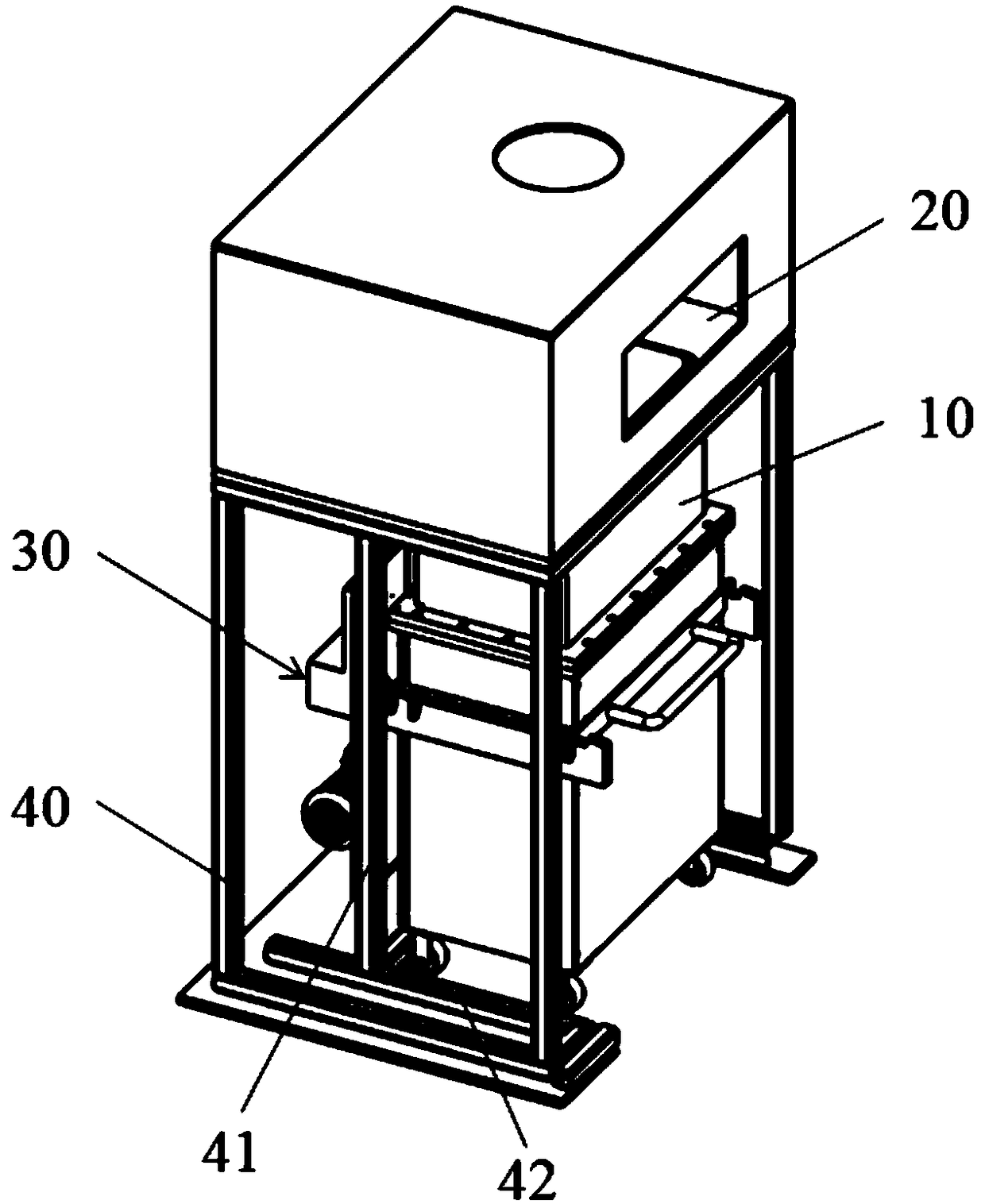
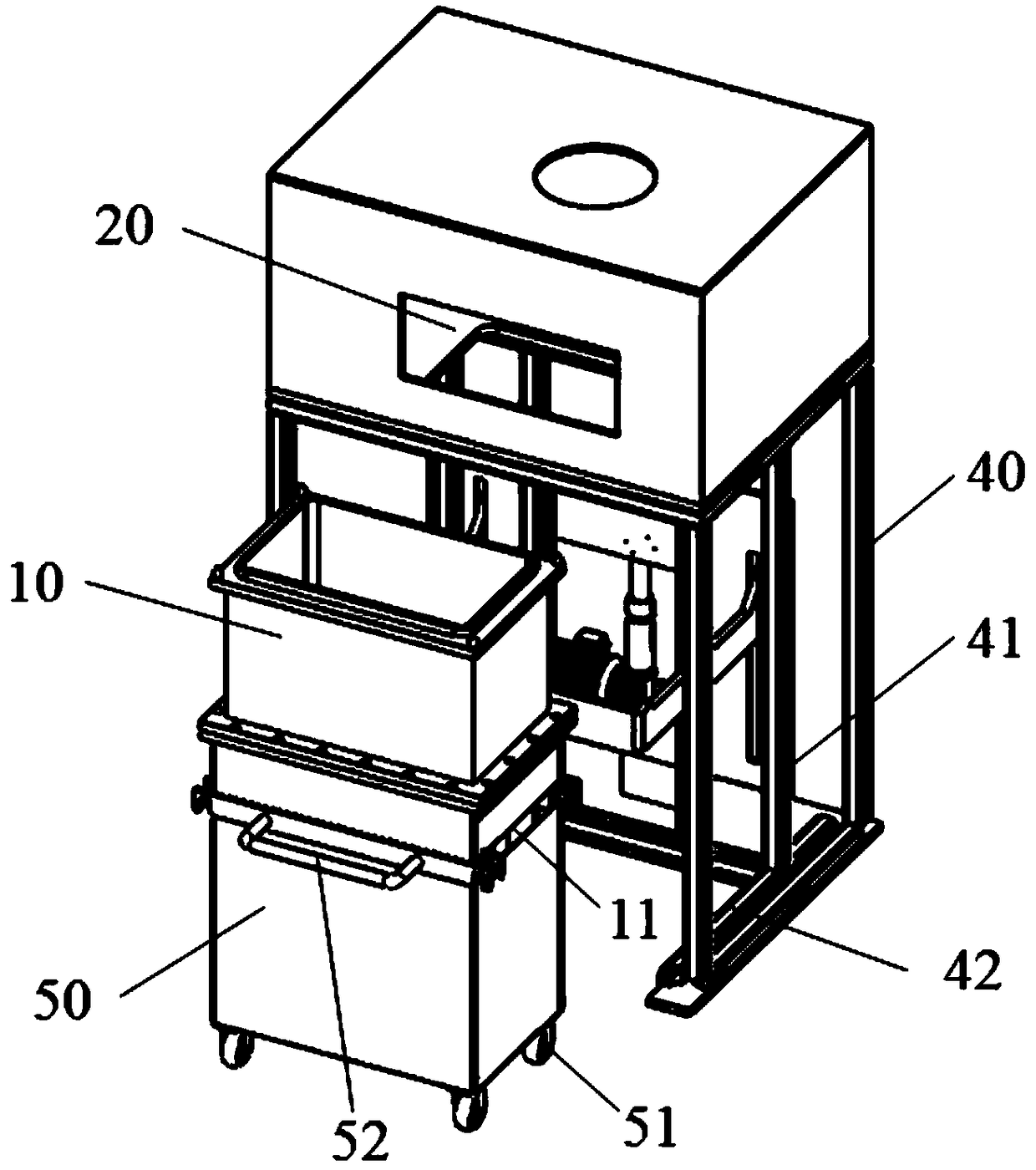
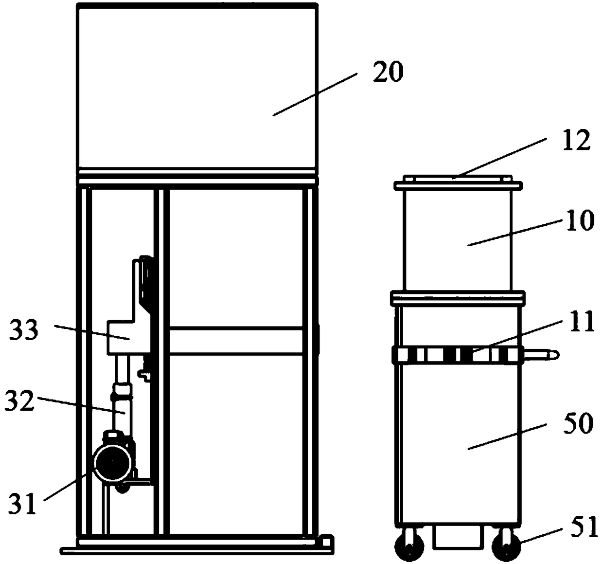
The invention relates to the field of 3D printing equipment, and particularly discloses a forming cylinder device for a 3D printer. The forming cylinder device comprises multiple movable forming cylinders, an electric control device fixedly connected to the forming cylinders and a lifting device used for achieving up-down transverse movement of the forming cylinders and achieving butt connection between the tops of the forming cylinders and the bottoms of forming cavities, the forming cavities are arranged above the lifting device, and the bottoms of the forming cavities are provided with clamping structures for being in clamped connection with the tops of the forming cylinders. By means of the forming cylinder device, product powder can be conveniently removed, products can also be conveniently taken out, equipment cleaning time is shortened, the product machining period is shortened, and the equipment utilization rate and production efficiency are improved.

Description

technical field [0001] The invention relates to the technical field of 3D printing equipment, in particular to a forming cylinder device for a 3D printer. Background technique [0002] In recent years, 3D printing technology has become increasingly mature and widely used in various fields. Existing 3D printers are only equipped with one set of molding cylinders, and they are all fixed on the equipment. After the printing is completed, it is necessary to stop the machine to clean the powder, and the cleaning of the powder must be done in the molding cavity. The space is small, it is inconvenient to operate, and the cleaning speed is slow. , because the printed product needs to be cleaned up before the finished product can be taken out, and then the substrate can be installed before the printing equipment can start the next processing task. During the period of cleaning the forming cylinder, the equipment cannot be started and operated, and the utilization rate of the equipme...

Claims


Application Information

Patent Timeline
Patent Type & Authority Applications(China)
IPC IPC(8): B29C64/20B29C64/393B29C64/30B33Y30/00B33Y50/02
CPCB29C64/20B29C64/30B29C64/393B33Y30/00B33Y50/02
Inventor 杨永强宋长辉张滨王迪
Owner GUANGZHOU LEIJIA TECH CO LTD
Learn More