Oily sludge treatment skid-mounted device and method
A sludge treatment and sludge technology is applied in the field of oily sludge treatment skid-mounted devices, which can solve the problems of secondary pollution, inconvenience caused by untimely treatment of soil pollution, and small amount of soil, so as to save construction costs and save the site. Space, the effect of reducing installation time
- Summary
- Abstract
- Description
- Claims
- Application Information
AI Technical Summary
Problems solved by technology
Method used
Image

Examples
Embodiment 1
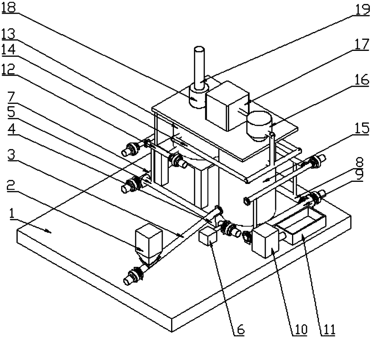
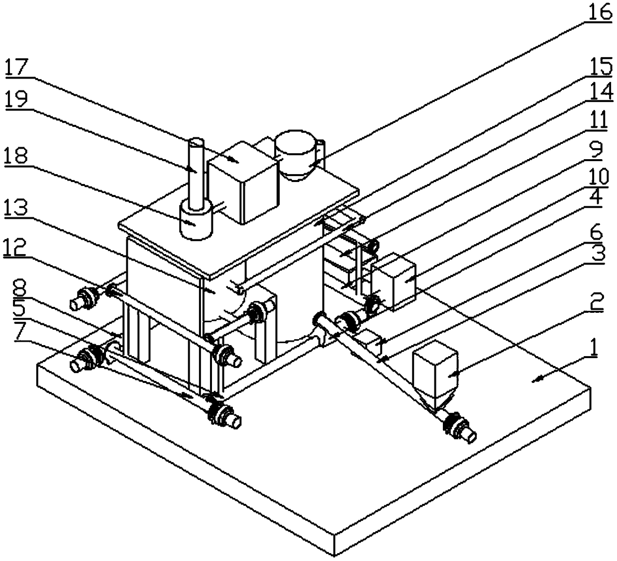
[0026] Such as figure 1 As shown, the skid-mounted device for oily sludge treatment in this embodiment consists of a base 1, a sludge blender 2, a screw conveyor 3, an upper hopper 4, a primary pyrolysis reactor 5, a nitrogen gas inlet system 6, a secondary thermal Decomposition reactor 7, third-stage pyrolysis reactor 8, fourth-stage pyrolysis reactor 9, cooling and dust prevention device 10, collection pool 11, gas manifold 12, gas collection tank 13, air condenser 14, oil-water recovery tank 15 , a cyclone separator 16, an absorption chamber 17, a low-temperature plasma gas processor 18, and a chimney 19.
[0027] A sludge blender 2 is installed on the base 1, and the oily sludge falls to the screw conveyor 3 from the outlet at the bottom of the sludge blender 2. The oily sludge is transported to the upper hopper 4 through the screw conveyor 3, and the outlet of the upper hopper 4 is connected with the inlet of the first-stage pyrolysis reactor 5 with a screw propeller, an...
Embodiment 2
[0030] The skid-mounted device of Embodiment 1 is used to process the oil-contaminated soil formed by the sudden oil leakage of the oil pipeline, and the specific methods are as follows:
[0031] 1. Use an excavator to dig out the oil-contaminated soil formed by the sudden oil leakage of the oil pipeline, transport it to the sludge blender 2, and blend it with the surrounding dry soil until the oil content is 18% and the moisture content is 56%. Then, the screw conveyor 3 is used to transport it to the upper hopper 4, and the sludge falls from the upper hopper 4 to the primary pyrolysis reactor 5 with a screw propeller through gravity.
[0032] 2. The nitrogen in the nitrogen gas intake system 6 enters from the air inlet of the primary pyrolysis reactor 5 with a screw propeller, and enters the secondary pyrolysis reactor 7 with a screw propeller through the connecting channel in turn. The three-stage pyrolysis reactor 8 with a screw propeller, the four-stage pyrolysis reactor ...
Embodiment 3
[0037] The skid-mounted device of Embodiment 1 is used to process the oil-contaminated soil formed by the sudden oil leakage of the oil pipeline, and the specific methods are as follows:
[0038] 1. Use an excavator to dig out the oil-contaminated soil caused by the sudden oil leakage of the oil pipeline, transport it to the sludge blender 2, and blend it with the surrounding dry soil until the oil content is 15% and the moisture content is 60%. Then, the screw conveyor 3 is used to transport it to the upper hopper 4, and the sludge falls from the upper hopper 4 to the primary pyrolysis reactor 5 with a screw propeller through gravity.
[0039] 2. The nitrogen in the nitrogen gas intake system 6 enters from the air inlet of the primary pyrolysis reactor 5 with a screw propeller, and enters the secondary pyrolysis reactor 7 with a screw propeller through the connecting channel in turn. The three-stage pyrolysis reactor 8 with a screw propeller, the four-stage pyrolysis reactor ...
PUM
 Abstract
Description
Claims
Application Information
 - R&D Engineer
- R&D Manager
- IP Professional
- Industry Leading Data Capabilities
- Powerful AI technology
- Patent DNA Extraction
Browse by: Latest US Patents, China's latest patents, Technical Efficacy Thesaurus, Application Domain, Technology Topic.
© 2024 PatSnap. All rights reserved.Legal|Privacy policy|Modern Slavery Act Transparency Statement|Sitemap