A self-locking cable grip

A technology of self-locking and clamping blocks, which is applied to bridge parts, erecting/assembling bridges, bridges, etc., can solve the problems of bolt loosening safety, long clamping blocks, cable strand scrapping, etc., to achieve convenient operation and avoid slippage Effect

Pending Publication Date: 2019-01-15
GUANGDONG PROVINCIAL CHANGDA HIGHWAY ENG
View PDF0 Cites 0 Cited by
  • Summary
  • Abstract
  • Description
  • Claims
  • Application Information

AI Technical Summary

Problems solved by technology

This form has a simple structure and reasonable stress, but there are three shortcomings: first, the workload of high-strength bolt locking on the construction site is relatively large; second, the high-strength bolts on the conventional During the operation, the mutual influence is relatively large, the pre-tightening degree of each bolt is difficult to be uniform, and individual bolts are prone to loosening, resulting in potential safety hazards; third, when the clamping block of the conventional cable gripper is not completely locked or the locking degree is insufficient Under normal circumstances, when using it to lift the cable strands, the cable gripper will slip on the strands, which may damage the galvanized layer of the strand steel wires, or cut the strand steel wires, causing the entire strand to be scrapped, and may also cause serious construction safety accident
It can be seen that in super-long-span suspension bridges, conventional cable grippers require more high-strength bolts, resulting in longer clamping blocks and heavier weight of cable grippers, which increases the difficulty and workload of manual operations, which in turn affects Efficacy and safety of main cable strand erection of suspension bridge
That is to say, the use of conventional cable grippers in the construction of super-long-span suspension bridges has limitations. Therefore, the invention of a new type of cable gripper with more reasonable structure, more reliable force, and easier operation has become a long-span bridge. The Urgent Need for Construction of Main Cable Strands of Suspension Bridge

Method used


Image

  • A self-locking cable grip
  • A self-locking cable grip
  • A self-locking cable grip

Examples


Embodiment Construction

[0031] Below, the present invention will be further described in conjunction with the accompanying drawings and specific implementation methods. It should be noted that, under the premise of not conflicting, the various embodiments described below or the technical features can be combined arbitrarily to form new embodiments. .

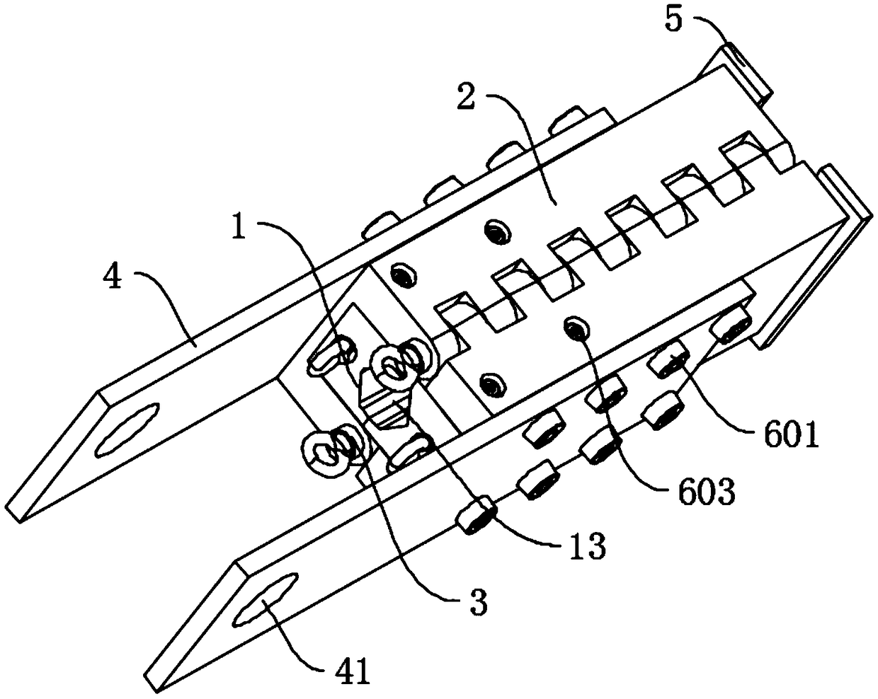
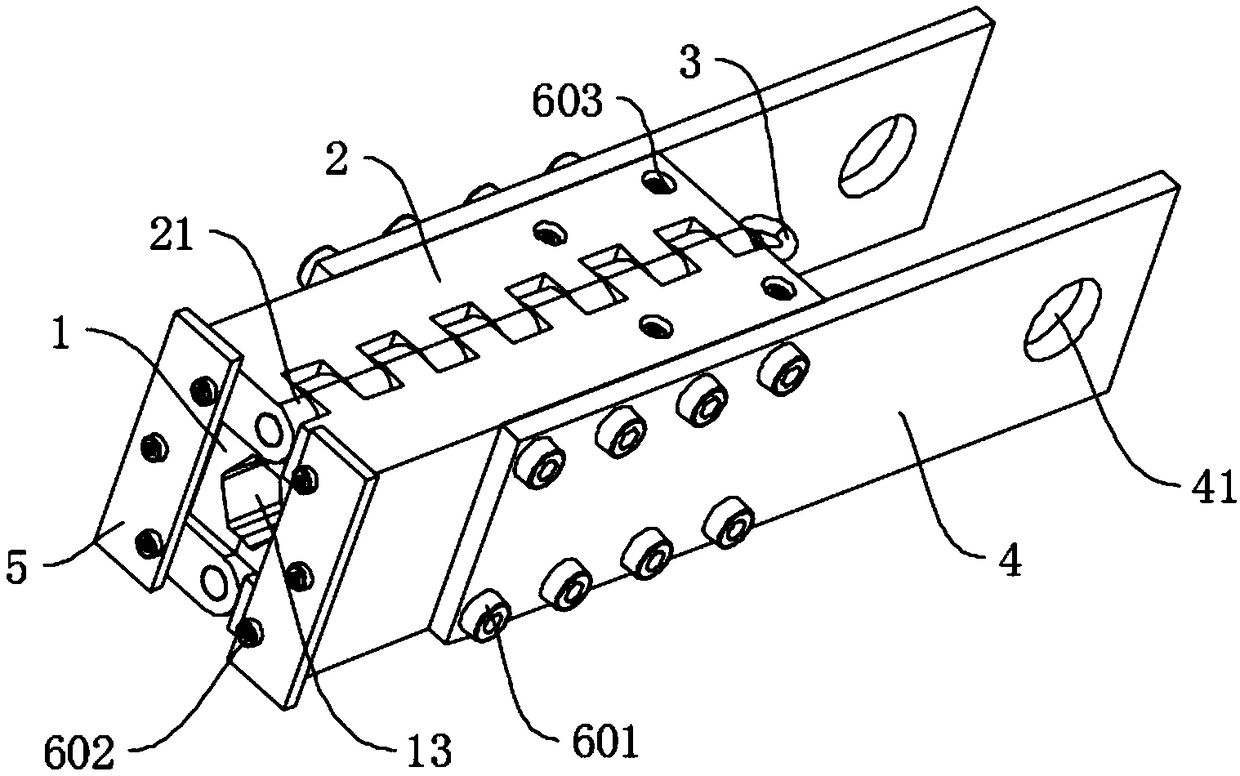
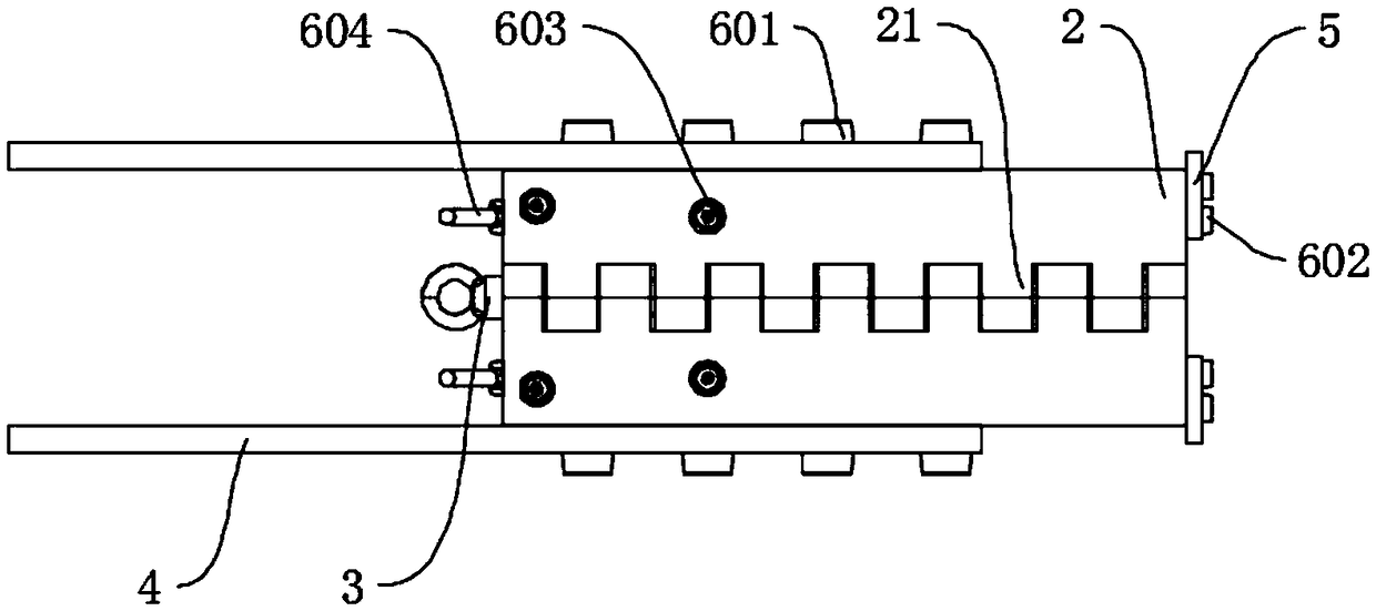
[0032] see Figure 1-Figure 6 , shows a self-locking cable grip device in a preferred embodiment of the present invention, which includes two clamping blocks 2 and two gripping blocks 1, wherein, between the two ends of the two clamping blocks 2 They are respectively connected by detachable hinges. When the first end of the two ends of the two clamping blocks 2 is disconnected, the two clamping blocks 2 rotate outward with the hinge point of the second end as the center of rotation and are in an open position. State, while turning inward with the hinge point as the center of rotation, the two clamping blocks 2 are in a closed state and locked by conne...


PUM


Abstract

A self-locking cable grip comprises two clamping blocks and two cable gripping blocks. The two ends of the two clamping blocks are respectively connected in a detachable hinge manner, and the two clamping blocks have an open state and a closed state. A grip block is mounted in the grip block and is slidable relative to the grip block, to extend or retract the gripping block. A wedge-shaped structure is formed between the clamping block and the cable grip block. As that two grip blocks are in the open state, the two grip blocks are in an open state, when the two grip blocks are in a closed state, the two grip blocks are in a closed state, notches are arranged at the positions where the two grip blocks are engaged, the notches of the two grip blocks form mounting grooves for cooperating withthe strands, and the shapes of the mounting grooves correspond to the outline shapes of the strands. The self-locking cable gripper can realize self-locking and convenient operation, and no slip phenomenon occurs after self-locking.

Description

technical field [0001] The invention relates to the field of main cable erection of suspension bridges, in particular to a self-locking cable gripper. Background technique [0002] The main cable of the suspension bridge is a component used to hoist the steel box girder of the suspension bridge. It is the main load-bearing component of the suspension bridge, and it transfers the weight of the suspension bridge to the main tower and anchorage. The main cables of suspension bridges basically use prefabricated parallel steel wire strands (P.P.W.S). Generally, each main cable is composed of tens or hundreds of strands, and each strand is composed of dozens or hundreds of prefabricated parallel steel wires. The steel wires of the cable strands are bundled into a whole by wrapping belts, and the section of the strands is generally hexagonal. [0003] The main cable strands of the suspension bridge are towed and erected on the catwalk from the anchorage on one side to the anchorag...

Claims


Application Information

Patent Timeline
IPC IPC(8): E01D19/16E01D21/00
CPCE01D19/16E01D21/00
Inventor 王晓佳罗超云罗人昆钟建锋张东曾房金钱张玉涛郑波涛吴育剑
Owner GUANGDONG PROVINCIAL CHANGDA HIGHWAY ENG
Why Eureka
Try Eureka