A kind of cast-in-place slab thickness controller

A cast-in-situ floor slab and controller technology, which is applied in the processing of building materials, construction, building structure, etc., can solve problems such as water pipe offset, increase load, affect decoration surface layer, etc., so as to avoid control errors and avoid impact deviation. Move and avoid the effect of fixing loose

Active Publication Date: 2020-10-16
SHANXI INSTALLATION GRP CO LTD
View PDF6 Cites 0 Cited by
  • Summary
  • Abstract
  • Description
  • Claims
  • Application Information

AI Technical Summary

Problems solved by technology

[0002] In building construction, floor thickness control has always been the key point of industry control. Too thick will increase the load and affect the decoration surface, while too thin will cause insufficient floor bearing capacity and cause danger.
[0003] In the construction of traditional buildings, manual measurement is used or water pipes are placed on the column inserted steel bars, and the height of the water pipes is used to control. The operation is cumbersome and the error is large, which is not suitable for pouring thickness control. In addition, the water pipes used in the construction of traditional buildings are not fixed firmly and are easy to Loose, when the external impact or the wind blows, it is easy to cause the water pipe to shift, resulting in control error, which is not conducive to the construction process, and the height of the water pipe used in the construction of traditional buildings cannot be stretched, the height cannot be adjusted, and it cannot be reused, which wastes resources; In view of these defects, it is necessary to design a cast-in-place slab thickness controller

Method used


Image

  • A kind of cast-in-place slab thickness controller
  • A kind of cast-in-place slab thickness controller
  • A kind of cast-in-place slab thickness controller

Examples


Embodiment Construction

[0026] The following will clearly and completely describe the technical solutions in the embodiments of the present invention with reference to the accompanying drawings in the embodiments of the present invention. Obviously, the described embodiments are only some, not all, embodiments of the present invention. Based on the embodiments of the present invention, all other embodiments obtained by persons of ordinary skill in the art without making creative efforts belong to the protection scope of the present invention.

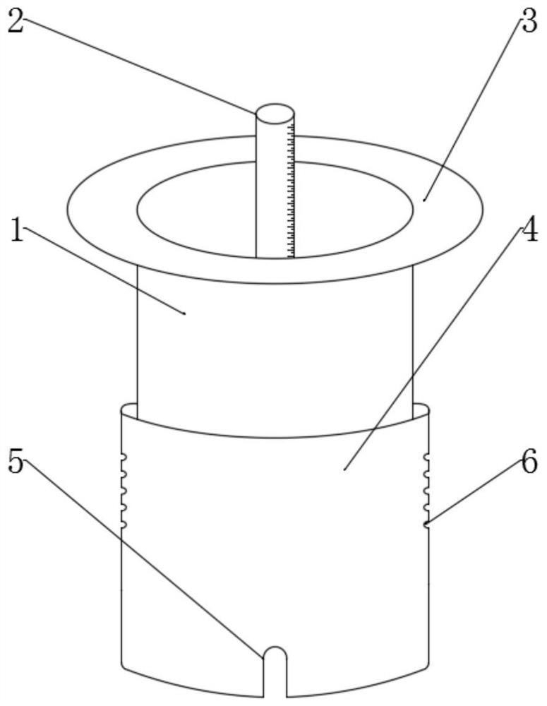
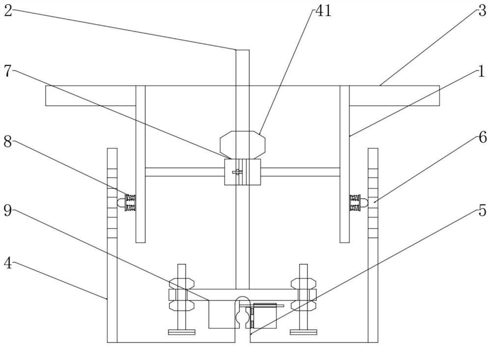
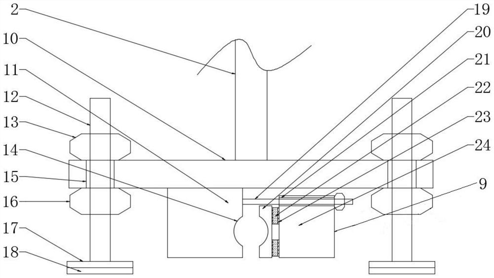
[0027] see Figure 1-6, the present invention provides a technical solution: a cast-in-place floor slab thickness controller, including a first hollow tube 1, a scale threaded rod 2, a stop plate 3, a second hollow tube 4, a steel bar hole 5, a telescopic hole 6, and a sliding assembly 7. The telescopic assembly 8, the fixing assembly 9 and the third hex nut sleeve 41, the bottom of the first hollow pipe 1 is sleeved with the second hollow pipe 4, the top of t...


PUM


Abstract

The invention discloses a cast-in-situ floor thickness controller comprising a first hollow tube, a scale threaded rod, a second hollow tube, steel holes, telescopic holes, a sliding assembly, telescopic assemblies, a fixation assembly and a third hexagon nut sleeve. The second hollow tube sleeves the bottom of the first hollow tube. Second spring plates are fixed at the two sides of the center atthe bottom of the first hollow tube by screws; second casing tubes are fixed at the two sides of the center at one end of each second spring plate by screws; and a first casing tube sleeves one end of each second casing tube. According to the cast-in-situ floor thickness controller, the fixation assembly has a simple structure and is convenient to operate; the fixation assembly is clamped and fixed firmly at the outer side of a floor steel bar by a first fixation block and a clamping plate; and plastic plates deform to generate elastic forces and thus the steel bar is clamped tightly so as toavoid fixation loosening. With first threaded columns and a bottom plate for supporting, the scale threaded rod is protected from being knocked to cause deviation by external forces, so that controlerror occurrence is avoided and construction can be carried out smoothly.

Description

technical field [0001] The invention relates to the technical field of construction engineering, in particular to a cast-in-place floor slab thickness controller. Background technique [0002] In building construction, the control of floor thickness has always been the key point of industry control. Too thick will increase the load and affect the decoration surface, while too thin will cause insufficient bearing capacity of the floor and cause danger. [0003] In the construction of traditional buildings, manual measurement is used or water pipes are placed on the column inserted steel bars, and the height of the water pipes is used to control. The operation is cumbersome and the error is large, which is not suitable for pouring thickness control. In addition, the water pipes used in the construction of traditional buildings are not fixed firmly and are easy to Loose, when the external impact or the wind blows, it is easy to cause the water pipe to shift, resulting in contro...

Claims


Application Information

Patent Timeline
Patent Type & Authority Patents(China)
IPC IPC(8): E04G21/10
CPCE04G21/10
Inventor 郭志恒殷涛许光明张铭向林郭启立柴雅琴马炜
Owner SHANXI INSTALLATION GRP CO LTD
Why Eureka
Try Eureka