
A two-stage vane ring assembly with adaptive thermal expansion for flue gas turbines

A flue gas turbine and vane ring technology, which is applied in the direction of engine components, mechanical equipment, machines/engines, etc., can solve the problem of affecting the rotor series motion and load, the difficulty of disassembling and replacing blades, and affecting the safety, reliability and stability of the flue gas turbine Work and other problems, to achieve the effect of improving efficiency, improving assembly efficiency and working reliability, and simple structure

Active Publication Date: 2021-03-16
AECC AVIATION POWER CO LTD
View PDF4 Cites 0 Cited by
  • Summary
  • Abstract
  • Description
  • Claims
  • Application Information

AI Technical Summary

Problems solved by technology

However, it brings difficulties to frequent disassembly and replacement of damaged blades. When reinstalling again, due to the deformation of the overall fixing ring, the overall fixing ring is not concentric with the rotor, and the gap between the rotor and the stator and the gap between the sealing parts change, which is serious. It will affect the series motion and load of the rotor, and directly affect the safe, reliable and stable operation of the flue gas turbine.

Method used


Image

  • A two-stage vane ring assembly with adaptive thermal expansion for flue gas turbines
  • A two-stage vane ring assembly with adaptive thermal expansion for flue gas turbines
  • A two-stage vane ring assembly with adaptive thermal expansion for flue gas turbines

Examples


Embodiment Construction

[0029] The present invention will be further described below in conjunction with the accompanying drawings.

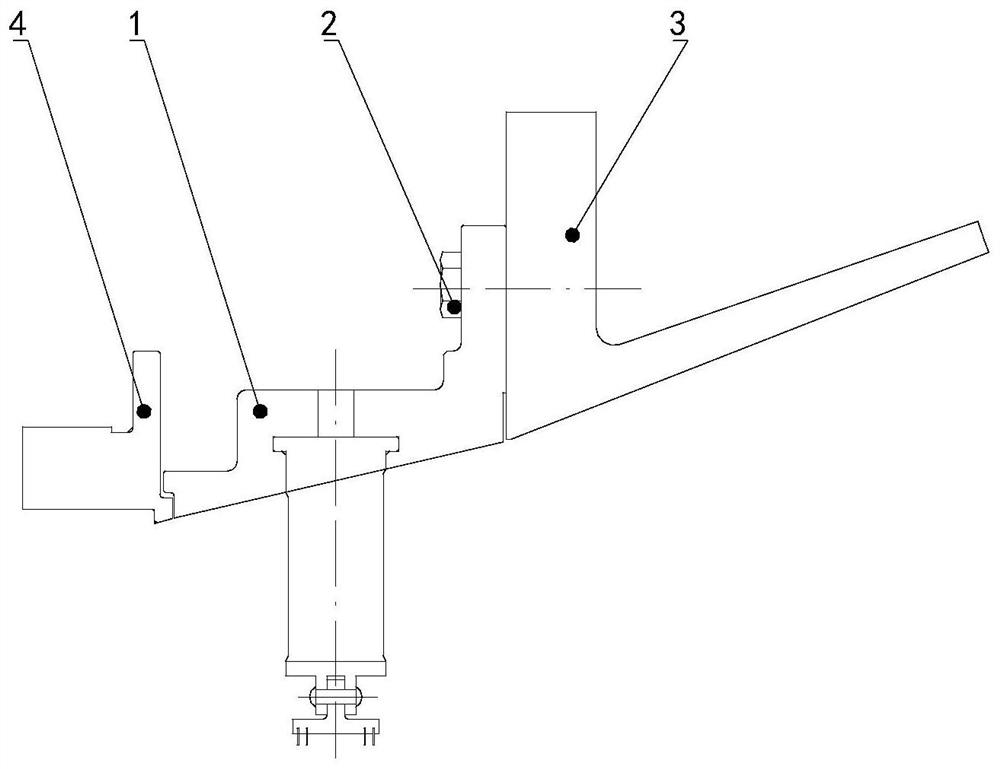
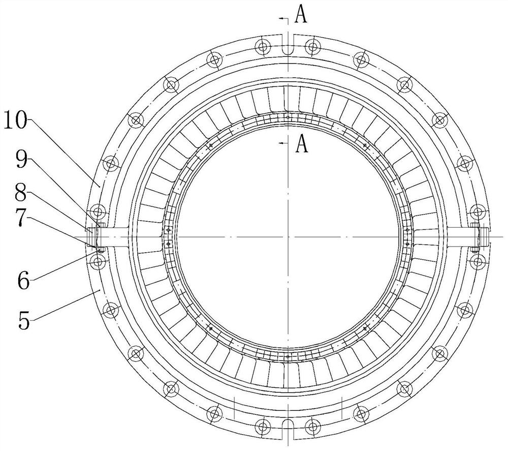
[0030] like Figure 1 to Figure 5 As shown, the present invention provides a second-stage vane ring assembly for self-adaptive thermal expansion of a flue gas turbine. Between the body diffuser assembly 3.

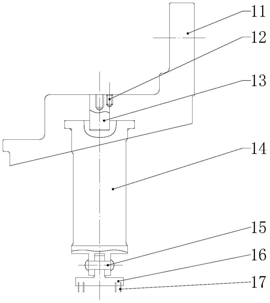
[0031] Secondary vane ring assembly 1 (eg image 3 (shown) includes secondary stationary vane fixing ring 11 , fixing screw 12 , second positioning pin 13 , secondary stationary vane 14 , round head rivet 15 , sealing ring assembly 16 and sealing piece 17 . The secondary vane ring assembly 1 is a cantilever support structure with one end fixed and one end freely expandable. It is fixed on the diffuser assembly 3 of the exhaust casing with the hexagon screw 2 . The Z-shaped structure is used to freely expand and connect with the primary vane ring assembly 4 (such as figure 1 shown).

[0032] Secondary vane fixing ring 11 (such as figure 2 shown) is machined ...


PUM


Abstract

The invention discloses a self-adaptive thermal expansion second-stage stator blade ring assembly of a flue gas turbine. The self-adaptive thermal expansion second-stage stator blade ring assembly ofthe flue gas turbine is mounted between a first-stage stator blade ring assembly and an exhaust shell pressure expander assembly of the flue gas turbine; the second-stage stator blade ring assembly comprises a second-stage stator blade fixed ring, a second-stage stator blade, a sealing ring assembly and sealing pieces, one end of the second-stage stator blade fixed ring is fixedly connected with the exhaust shell pressure expander assembly, and the other end of the second-stage stator blade fixed ring is connected with the first-stage stator blade ring assembly in a free expansion mode; T-shaped grooves distributed along the circumference are adopted in the second-stage stator blade fixed ring, a T-shaped plate of the outer edge of the second-stage stator blade is mounted in a circular groove of the second-stage stator blade fixed ring in a hanging mode, a redial pin hole is adopted along the circumference every several blades, and locating pins are mounted for fixation; and a convex lug with through holes of two layers is adopted in an inner edge plate of the second-stage stator blade to fix the sealing ring assembly to the convex lug, the sealing pieces distributed along the circumference are adopted on the sealing ring assembly, and the sealing pieces are matched with a wheel disc. The second-stage stator blade is mounted to form an airflow channel, and energy conversion iscompleted.

Description

technical field [0001] The invention relates to a second-stage vane ring assembly for self-adaptive thermal expansion of a flue gas turbine, which is applied to a device of a catalytic cracking waste heat energy recovery unit in the petrochemical industry. Background technique [0002] At present, the flue gas turbine widely used in catalytic cracking waste heat energy recovery units in the petrochemical industry is the core device of the entire unit, and the secondary stator vane ring assembly is an important component that converts part of the heat energy of the flue gas flow passing through it into kinetic energy. To achieve the effect of energy recovery. The secondary vane ring assembly is surrounded by the flue gas flow, and the flue gas temperature is high and unevenly distributed, which easily leads to ablation of the blades; at the same time, the flue gas contains oxidants such as sulfur and catalyst particles, which have a greater corrosion effect on the blades , e...

Claims


Application Information

Patent Timeline
Patent Type & Authority Patents(China)
IPC IPC(8): F01D9/04
CPCF01D9/041F01D9/042
Inventor 闫庆安郭永强张三多章宏标
Owner AECC AVIATION POWER CO LTD
Learn More