Oil-gas separation structure and system thereof
A separation structure, oil and gas technology, applied in the direction of engine components, machines/engines, mechanical equipment, etc., can solve the problems of poor dirt resistance, poor separation effect, easy clogging, etc., and meet the requirements of low qualification requirements, simple structure, materials and processes The effect of request reduction
- Summary
- Abstract
- Description
- Claims
- Application Information
AI Technical Summary
Problems solved by technology
Method used
Image

Examples
Example Embodiment
[0061] Example one
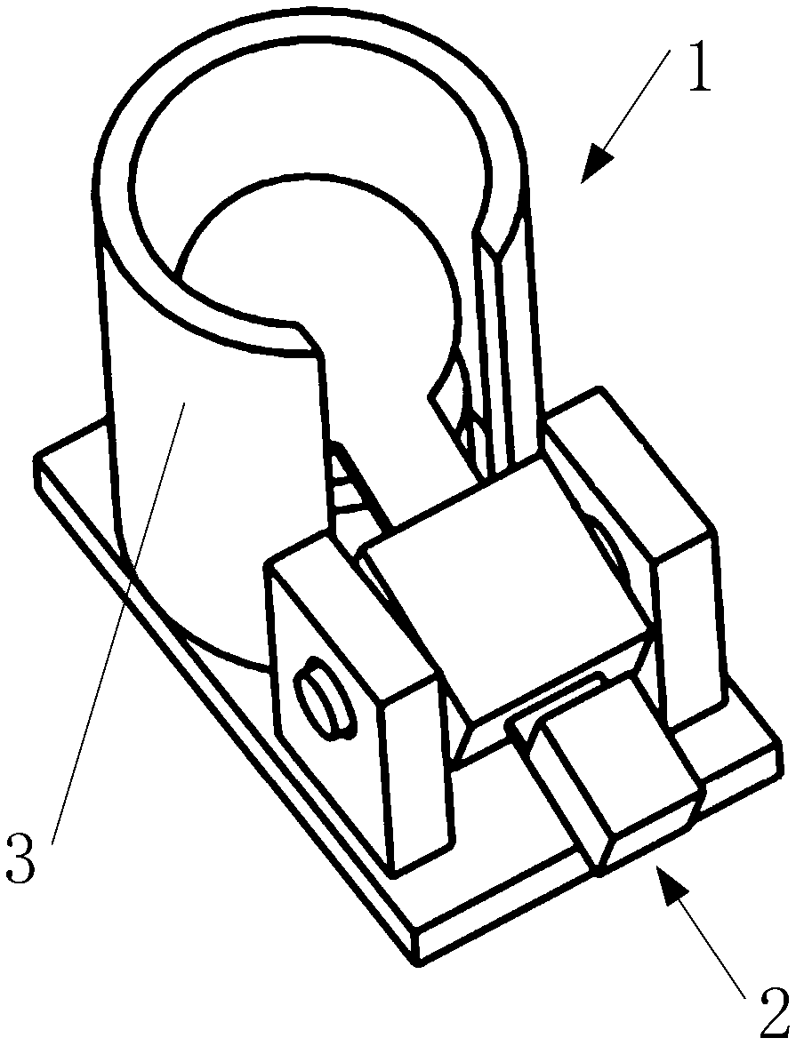
[0062] See Figure 1-Figure 7 As shown, this embodiment provides an oil-gas separation structure, which includes a valve body 1 and a valve plate assembly 2;
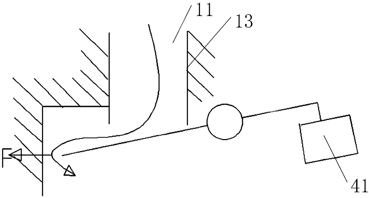
[0063] The valve body 1 is provided with a ventilation channel 11;
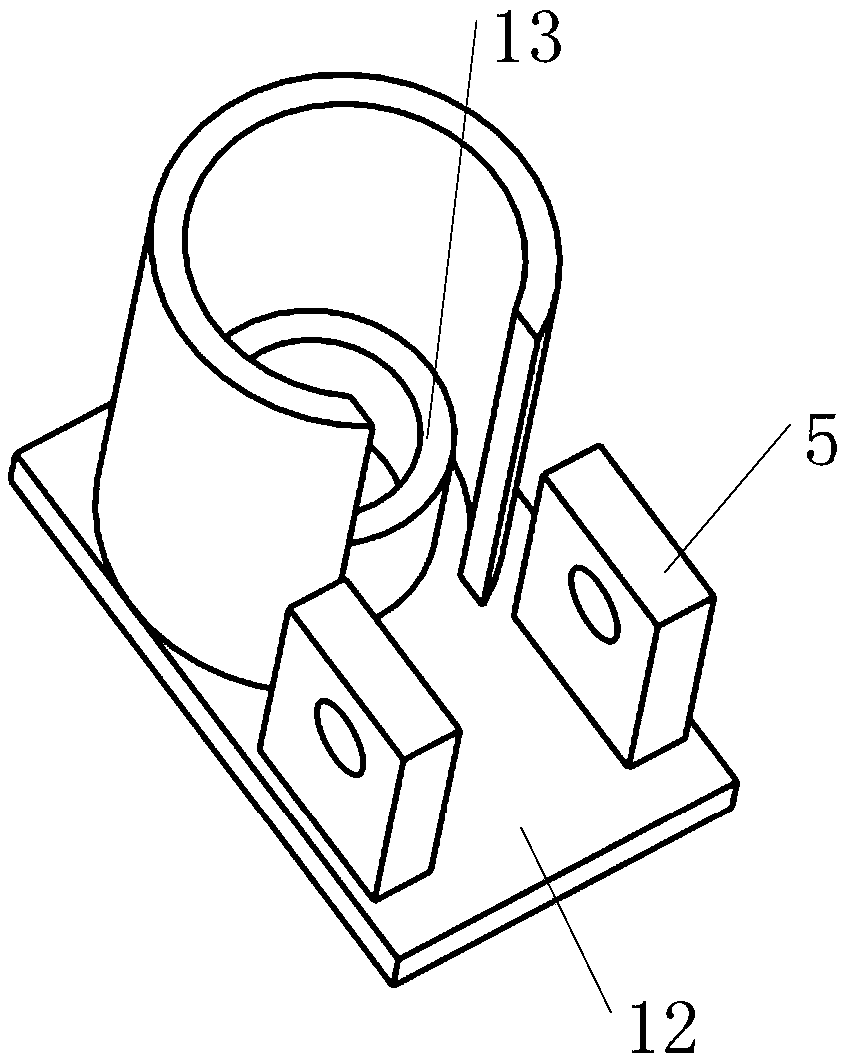
[0064] See figure 2 As shown, one end of the air passage 11 is provided with a baffle 3;
[0065] The valve plate assembly 2 is rotatably connected with the valve body 1, and the valve plate 23 of the valve plate assembly 2 corresponds to an end of the ventilation channel 11 close to the baffle 3;
[0066] The valve plate 23 always has a tendency to snap onto the ventilation channel 11;
[0067] When the airflow flows along the vent passage 11 to the end close to the baffle 3, it can impact the valve plate 23 to make the valve plate assembly 2 rotate relative to the valve body 1, so that the vent passage 11 Open, the air flow hits the baffle 3 along the valve plate 23, and flows out from the gap between the valve plate 23 and the baffle 3, ...
Example Embodiment
[0103] Example two
[0104] The second embodiment provides an oil-gas separation system. The oil-gas separation system includes the oil-gas separation structure described in the first embodiment. The technical features of the oil-gas separation structure disclosed in the first embodiment are also applicable to this embodiment. The technical features of the disclosed oil-gas separation structure will not be repeated. The implementation of the oil and gas separation system will be further described in detail below in conjunction with the accompanying drawings.
[0105] To save space, the improved features of this embodiment are also reflected in Figure 8-10 In, therefore, combined Figure 8-10 The solution of this embodiment will be described.
[0106] See Figure 8-10 As shown, the oil-gas separation system provided in this embodiment includes the oil-gas separation structure;
[0107] See Picture 9 with Picture 10 As shown, there are multiple vent passages 11 on the valve body ...
PUM
 Abstract
Description
Claims
Application Information
 - R&D Engineer
- R&D Manager
- IP Professional
- Industry Leading Data Capabilities
- Powerful AI technology
- Patent DNA Extraction
Browse by: Latest US Patents, China's latest patents, Technical Efficacy Thesaurus, Application Domain, Technology Topic.
© 2024 PatSnap. All rights reserved.Legal|Privacy policy|Modern Slavery Act Transparency Statement|Sitemap