Application method of wind motor

A wind engine and wind power technology, applied in the direction of wind engine control, wind engine, wind engine for storing electricity, etc., can solve the problems of low efficiency of wind power generation, waste of wind power, and inability to completely eliminate damage caused by strong winds, etc., to improve practicality Sex and convenience, the overall structure is reasonable and ingenious, and the effect of high use and promotion value

Inactive Publication Date: 2019-01-15
XIANJU YUNLI ELECTRONICS TECH CO LTD
View PDF0 Cites 13 Cited by
  • Summary
  • Abstract
  • Description
  • Claims
  • Application Information

AI Technical Summary

Problems solved by technology

[0002] When people use wind power to work, they often use wind power to do work traditionally, such as windmills, or simply use separation to generate power, and use wind power to do work. The efficiency of wind power generation is not high, so there is a need for a method of using a wind power engine that can do work when it needs to do work, use it for power generation and storage when it is idle, and maximize the use of separation
[0003] There are also some wind power engines now, and these engines are often easily damaged in strong winds. Now some equipment is equipped with blade locking devices to lock the blades when the wind is too strong, which increases the load on the blades and cannot completely eliminate the damage caused by strong winds. damaged equipment

Method used

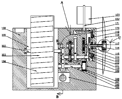

Image

  • Application method of wind motor
  • Application method of wind motor
  • Application method of wind motor

Examples


Embodiment Construction

[0022] All features disclosed in this specification, or steps in all methods or processes disclosed, may be combined in any manner, except for mutually exclusive features and / or steps.

[0023] Any feature disclosed in this specification (including any appended claims, abstract and drawings), unless expressly stated otherwise, may be replaced by alternative features which are equivalent or serve a similar purpose. That is, unless expressly stated otherwise, each feature is one example only of a series of equivalent or similar features.

[0024] In describing the present invention, it should be understood that the terms "center", "longitudinal", "transverse", "length", "width", "thickness", "upper", "lower", "front", " Orientation indicated by rear, left, right, vertical, horizontal, top, bottom, inside, outside, clockwise, counterclockwise, etc. The positional relationship is based on the attached figure 1 The orientations or positional relationships shown are only for the c...


PUM


Abstract

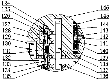
The invention provides an application method of a wind motor. The wind motor comprises a motor body and a water storage cavity with an upward opening, and the water storage cavity is formed in the left side of the motor body; a water drawing device is arranged in the water storage cavity, and the motor body is internally provided with a first cavity and a first transmission cavity; a vertical axiswind power device is arranged in the first cavity and comprises a first rotating shaft rotatably arranged in the top wall of the first cavity, the downwardly-extending tail end of the first rotatingshaft extends into the tail end of the first cavity, and a first bevel gear is fixedly mounted at the tail end of the first rotating shaft. The application method has the advantages that the wind motor is more reasonable and ingenious in overall structure, and quite convenient to use; equipment blades are prevented from being damaged by wind power through a protection device; the rotating direction of an output shaft of equipment can be kept constantly consistent through a direction adjusting device; the equipment can be switched to power generation or work, practicability and convenience of the equipment are improved, and accordingly, high application and promotion value is achieved.

Description

technical field [0001] The invention relates to the field of wind power applications, in particular to a method for using a wind power engine. Background technique [0002] When people use wind power to work, they often use wind power to do work traditionally, such as windmills, or simply use separation to generate power, and use wind power to do work. The efficiency of wind power generation is not high, so there is a need for a method of using a wind power engine that can do work when it needs to do work, and use it for power generation and storage when it is idle, so that it can be separated and utilized to the greatest extent. [0003] There are also some wind power engines now, and these engines are often easily damaged in strong winds. Now some equipment is equipped with blade locking devices to lock the blades when the wind is too strong, which increases the load on the blades and cannot completely eliminate the damage caused by strong winds. Equipment damaged. [00...

Claims


Application Information

Patent Timeline
Patent Type & Authority Applications(China)
IPC IPC(8): F03D9/11F03D15/00F03D7/04F03D9/20
CPCF03D7/0204F03D7/0276F03D9/11F03D9/20F03D15/00Y02E10/72Y02E70/30
Inventor 张颢奕
Owner XIANJU YUNLI ELECTRONICS TECH CO LTD
Why Eureka
Try Eureka