Eureka AIR delivers breakthrough ideas for toughest innovation challenges, trusted by R&D personnel around the world.

Sluice valve and manufacturing process of valve body lining part

A technology for a lining piece and a knife gate valve, which is applied in the field of the manufacturing process of the knife gate valve and the lining piece in the valve body, can solve the problems of increasing the use and maintenance cost, the valve body cannot be sealed, and the valve body is worn, so as to reduce the maintenance cost and improve the Sealing, easy maintenance effect

Active Publication Date: 2019-01-15
WENZHOU CHISUN VALVE MFG CO LTD
View PDF7 Cites 3 Cited by
  • Summary
  • Abstract
  • Description
  • Claims
  • Application Information

AI Technical Summary

Problems solved by technology

[0003] At present, the knife gate valves used in the pipelines of the slurry system are ordinary knife gate valves with carbon steel or ductile iron valve bodies. The slurry medium directly contacts with the flow channel of the valve body. Friction, the valve body will wear out in a short period of time. Once the anti-corrosion layer on the surface of the valve body is worn off, the corrosion of the valve body will be accelerated, so that the valve body will not be able to seal quickly or even be damaged. Cost, while replacing the guide groove of the new valve body, the gate plate needs to be re-run-in with the side sealing groove of the valve body, which will also bring some hidden dangers

Method used


Image

  • Sluice valve and manufacturing process of valve body lining part
  • Sluice valve and manufacturing process of valve body lining part
  • Sluice valve and manufacturing process of valve body lining part

Examples


Embodiment Construction

[0030] Refer to attached Figure 1 to Figure 8 A knife gate valve of the present invention will be described in further detail.

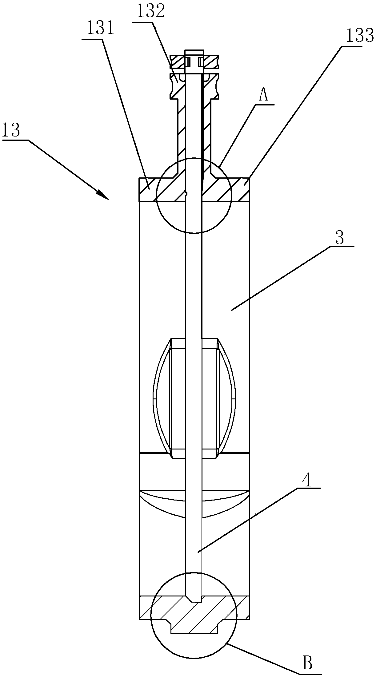
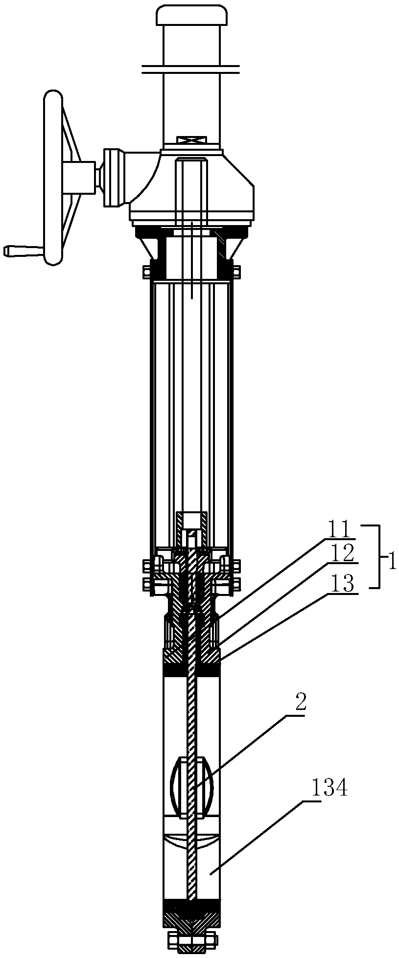
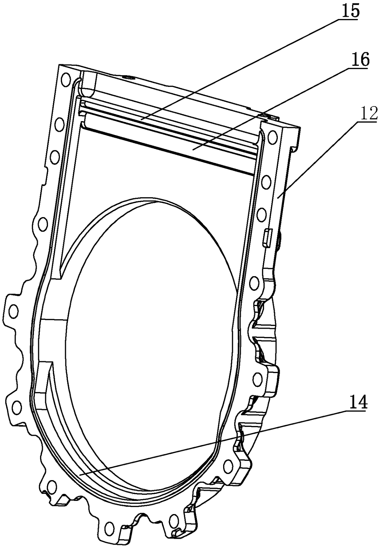
[0031] From figure 1 It can be seen that a knife gate valve includes a valve body 1 and a gate plate 2, the valve body 1 includes a left valve body 11, a right valve body 12 and a valve inner lining 13, and the valve inner lining 13 adopts a specific elastic The non-metallic material is integrally formed, and the elastic non-metallic material can be wear-resistant polyurethane and other rubber materials, wherein the left valve body 11 and the right valve body 12 are made of traditional metal materials, and the left valve body 11 and the right valve body 12 are respectively located on the left and right sides of the valve body liner 13, the left valve body 11 and the right valve body 12 are pressed against the valve body liner 13 by screws, wherein the opposite surfaces of the left valve body 11 and the right valve body 12 are respectively A sealin...


PUM


Abstract

The invention discloses a sluice valve. A valve body comprises a left valve body, a right valve body and a valve body lining part, the valve body lining part is integrally formed by rubber materials,the left valve body and the right valve body are located on the left side and the right side of the valve body lining part respectively, the left valve body and the right valve body are used for tightly pressing the valve body lining part through screws, a through hole matched with the valve hole and a gate plate lifting groove communicating with the through hole are formed in the valve body lining part, and a side sealing groove and a bottom sealing groove are formed in the gate plate lifting groove; and when the gate plate moves downwards to seal the valve hole through the gate plate liftinggroove, the side edge of the gate plate is arranged in the side face sealing groove, and the U-shaped top end face of the gate plate is tightly pressed in the bottom sealing groove. The sluice valvehas a double-sealing-form effect simultaneously, so that the sealing of the gate valve can be effectively improved; and when the valve is opened, the gate plate is moved upwards, so that the inner side wall of the valve hole is bounced, and sundries are prevented from being deposited.

Description

technical field [0001] The invention relates to the field of valves, more specifically, it relates to a knife gate valve and a manufacturing process of a valve inner lining. Background technique [0002] Knife gate valve is also called knife gate valve and knife type slurry valve. Its opening and closing parts are gates. The direction of movement of the gates is perpendicular to the direction of the fluid. The medium is cut off by the blade-shaped gates that can cut fiber materials. There is actually no cavity in the valve body, and the gate moves up and down in the side sealing groove, and is pressed tightly against the valve seat by the lug at the bottom, wherein a sealing strip is set in the side sealing groove to closely adhere to the plane of the gate to form a seal. To ensure the tightness of the knife gate valve. [0003] At present, the knife gate valves used in the pipelines of the slurry system are ordinary knife gate valves with carbon steel or ductile iron valve...

Claims


Application Information

Patent Timeline
Patent Type & Authority Applications(China)
IPC IPC(8): F16K3/02F16K3/314F16K3/316F16K3/30F16K27/04B29C45/14
CPCB29C45/14F16K3/0227F16K3/0281F16K3/30F16K3/314F16K3/316F16K27/044
Inventor 姜日静
Owner WENZHOU CHISUN VALVE MFG CO LTD
Why Eureka
Eureka Blog
Learn More