
Automatic measurement method for radiated sound power insertion loss of sound intensity probe

A technology of sound intensity probe and measurement method, which is applied in the direction of vibration measurement in fluid, measurement vibration, measurement device, etc., and can solve the problem that the anechoic pool cannot simulate the deep sea pressure environment, etc.

Inactive Publication Date: 2019-01-15
CSSC SYST ENG RES INST
View PDF6 Cites 4 Cited by
  • Summary
  • Abstract
  • Description
  • Claims
  • Application Information

AI Technical Summary

Problems solved by technology

[0003] Based on this, the inventors of the present invention found that ordinary anechoic pools cannot simulate the deep-sea pressure environment, and a special pressurized anechoic water tank is required for measurement

Method used


Image

  • Automatic measurement method for radiated sound power insertion loss of sound intensity probe
  • Automatic measurement method for radiated sound power insertion loss of sound intensity probe
  • Automatic measurement method for radiated sound power insertion loss of sound intensity probe

Examples


Embodiment 1

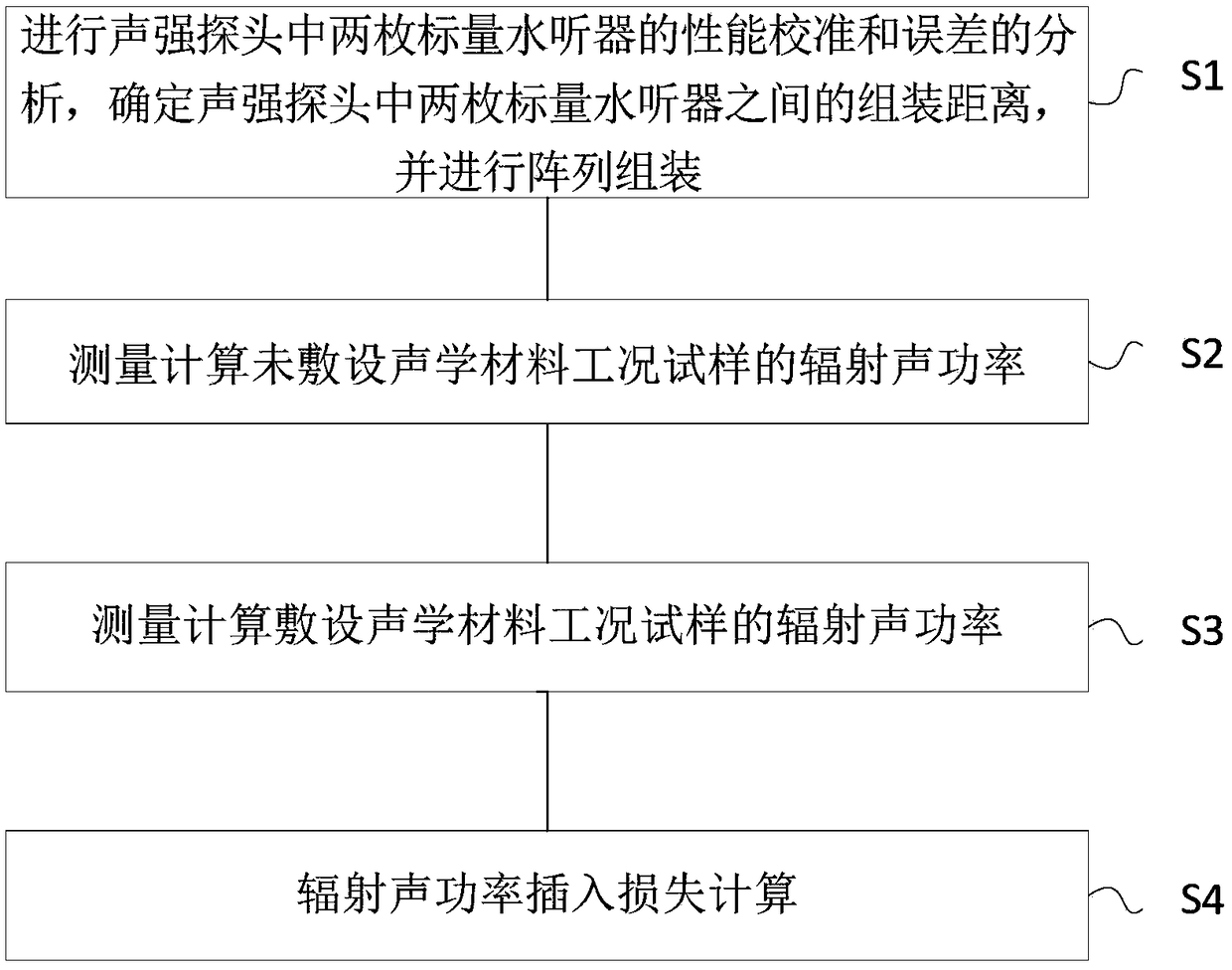
[0079] figure 1 A flowchart showing an automatic measurement method for insertion loss of radiated sound power based on a sound intensity probe provided by an embodiment of the present invention, the method may be executed by an electronic device, such as a terminal device or a server device. In other words, the method can be executed by software or hardware installed on the terminal device or the server device. The server includes, but is not limited to: a single server, a server cluster, and the like. As shown in the figure, the method includes the following steps.

[0080] Step S1: Perform performance calibration and error analysis of the two scalar hydrophones in the sound intensity probe, determine the assembly distance between the two scalar hydrophones in the sound intensity probe, and perform array assembly

[0081] Sound intensity probe assembly and sound intensity probe array installation, including the assembly of each sound intensity probe by two pressure-resista...

Embodiment 2

[0160] An embodiment of the present invention provides a non-transitory (non-volatile) computer storage medium, the computer storage medium stores computer-executable instructions, and the computer-executable instructions can execute the method in any of the above-mentioned method embodiments, and achieve the same technical effect.

Embodiment 3

[0162] An embodiment of the present invention provides a computer program product, the computer program product includes a computer program stored on a non-transitory computer-readable storage medium, the computer program includes program instructions, and when the program instructions are executed by a computer , causing the computer to execute the methods described in the above aspects, and achieve the same technical effect.


PUM


Abstract

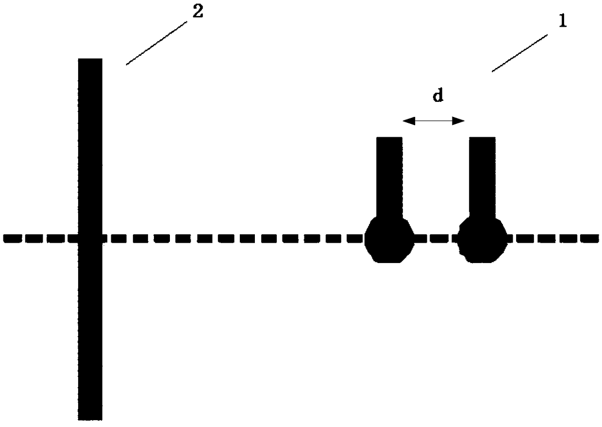
The embodiment of the invention relates to an automatic measurement method for the radiated sound power insertion loss of a sound intensity probe. The automatic measurement method comprises the stepsthat the assembly distance d between two scalar hydrophones in the sound intensity probe is determined and meets a formula (please see the specifications for the formula), wherein lambda is the wavelength of a sound wave in water; the mounting positions of the two scalar hydrophones in the sound intensity probe are determined to enable the connecting line direction of the two scalar hydrophones topoint to a tested structure object, and the positions of all sound intensity probe array elements are determined according to the main lobe direction of the sound intensity probe; the radiated soundpower of a sample under the work condition without laying acoustic materials is measured and calculated; the radiated sound power of the sample under the work condition of laying the acoustic materials is measured and calculated; and the radiated sound power insertion loss is calculated. According to the automatic measurement method for the radiated sound power insertion loss of the sound intensity probe, the influence of an interface on test results during radiated sound power measurement in a large pressure muffler water tank can be reduced, and meanwhile, the structure radiated sound powerinsertion loss can be automatically measured.

Description

technical field [0001] The patent of the present invention relates to the field of measurement methods for radiated sound power, specifically an automatic measurement method for insertion loss of radiated sound power based on a sound intensity probe. Background technique [0002] With the continuous development of science and technology and the increasing demand for ocean exploration, a large number of new underwater structures have been developed and manufactured. These underwater structures will generate radiation noise, which will adversely affect marine life and ship navigation. People reduce radiated noise by laying various acoustic materials on underwater structures. The measurement of the radiated sound power insertion loss of acoustic materials can evaluate the suppression effect of acoustic materials on structural radiated noise. [0003] Based on this, the inventors of the present invention have found that common anechoic pools cannot simulate the deep-sea pressur...

Claims


Application Information

Patent Timeline
IPC IPC(8): G01H3/10G01H3/14
CPCG01H3/10G01H3/14
Inventor 闫孝伟丁晓冬向平苏琳黄永强陈晓芳
Owner CSSC SYST ENG RES INST
Learn More