
Method and device for monitoring transmission tower

A transmission tower and unified technology, applied in the field of transmission tower monitoring methods and devices, can solve problems such as strong environmental noise, affecting imaging quality, and increasing imaging difficulty

Active Publication Date: 2019-01-15
国网四川省电力公司电力应急中心
View PDF7 Cites 4 Cited by
  • Summary
  • Abstract
  • Description
  • Claims
  • Application Information

AI Technical Summary

Problems solved by technology

[0004] The technical problem to be solved by the present invention is: due to the special structure of the high-voltage transmission tower and the complex terrain where it is located, there is relatively strong environmental noise in the observation image, which greatly increases the difficulty of imaging, and it is easy to cause false imaging, which affects the imaging quality. The present invention provides a method and device for monitoring power transmission towers that solve the above problems

Method used


Image

  • Method and device for monitoring transmission tower
  • Method and device for monitoring transmission tower
  • Method and device for monitoring transmission tower

Examples


Embodiment 1

[0064] This embodiment provides a transmission tower monitoring method, the specific operation method is as follows:

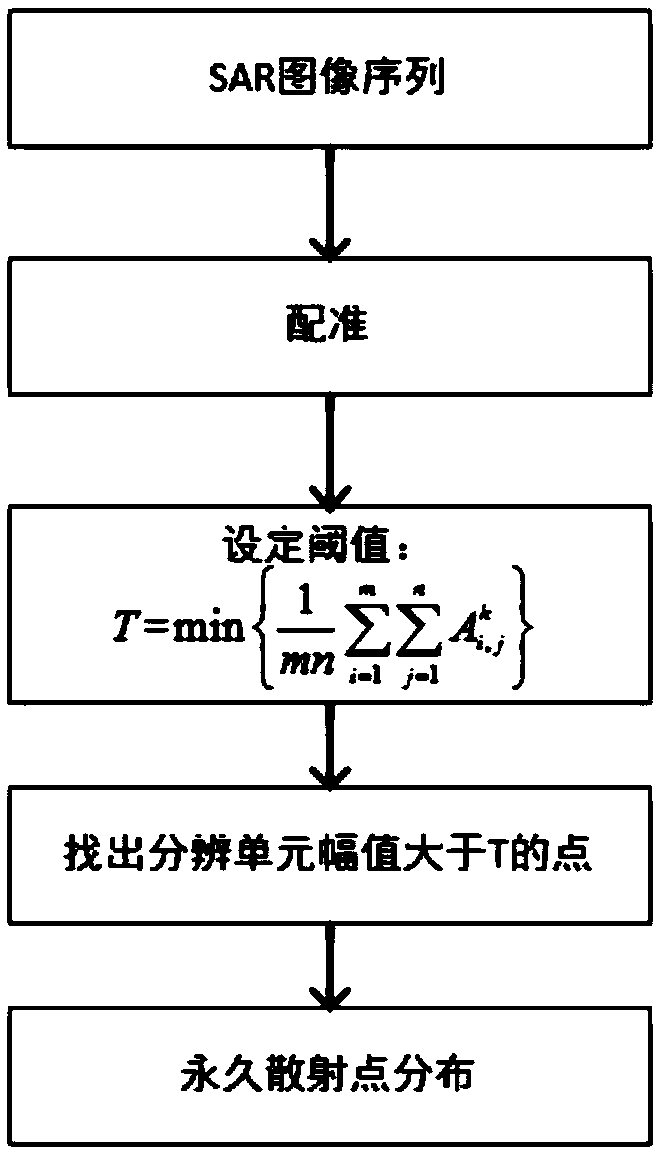
[0065] Step A: Obtain the SAR image sequence of the same power transmission tower area through satellite radars with different time sequences and different tracks, and perform image registration to obtain image data, so that the pixels with the same name in the image sequence correspond to the same ground features; and remove the image sequence Skew and phase compensation processing operations to obtain a set of observation data [S 1 ,S 2 ,L,S m ], where S m Indicates the mth image;

[0066] Wherein, the image parameters include S m and S m-1 Vertical baseline b between observations m and time base t m , the incident angle size θ, the central slant distance length r, the wavelength λ, the number of observations m, the azimuth resolution and the range resolution.

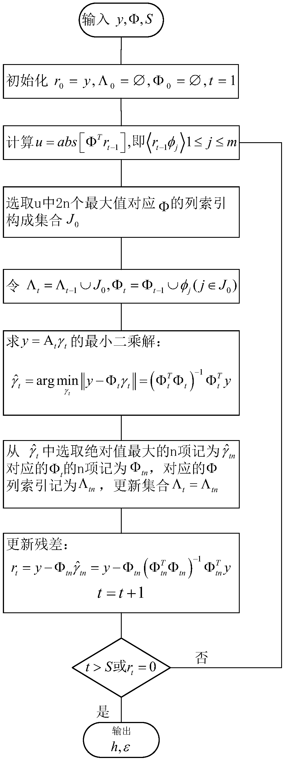
[0067] Step B, extracting the permanent scattering points located on the transmission tow...

Embodiment 2

[0099] This embodiment provides a device for realizing the method for monitoring a power transmission tower described in Embodiment 1, including a preprocessing module, a permanent scattering point extraction module and a reconstruction module;

[0100] The preprocessing module is used to extract image parameters in the SAR image sequence, and perform preprocessing to obtain observation data;

[0101] The permanent scattering point extraction module is used to screen the permanent scattering points according to the amplitude information in the SAR image;

[0102] The reconstruction module is used to reconstruct the elevation information and deformation rate information of the transmission tower corresponding to the permanent scattering point according to the observation data.

Embodiment 3

[0104] Application of the methods and devices provided in Embodiments 1 and 2: In this embodiment, 18 two-dimensional SAR images of the power transmission tower area are provided. image 3 It is the cropped original SAR image, the background of the image is the mountain surface and vegetation, the transmission tower is located in the highlighted part of the image, and the outline of the transmission tower can be seen more clearly. SAR images are preprocessed by registration, de-skewing and phase compensation, and the SAR image data (SARscape) are obtained by SARscape commercial software. m and S m-1 Vertical baseline b between observations m and time base t m , the incident angle size θ, the central slant distance length r, the wavelength λ, the number of observations m, the azimuth resolution and the range resolution.

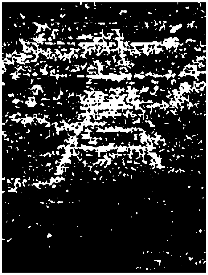
[0105] Figure 4(a) and Figure 4(b) are the distribution diagrams of permanent scattering points. Obtained by permanent scatter point screening on the SAR ...


PUM


Abstract

The invention discloses a method and device for monitoring a transmission tower. The method comprises the following steps: acquiring an SAR image sequence of the same transmission tower area through satellite radars with different timings and different tracks, and conducting a preprocessing operation to obtain observation data and image parameters; extracting permanent scattering points on the transmission tower in the SAR image sequence to obtain stable and reconfigurable candidate points; and reconstructing elevation information and deformation rate information of the permanent scattering points corresponding to the position of the transmission tower by using the compressed sampling matching a tracking algorithm according to the observed data. By using the method and device for monitoring a transmission tower provided by the invention, the transmission tower can be monitored from the SAR image sequence, the environmental noise is effectively suppressed, and the elevation informationand deformation rate information of the transmission tower are extracted.

Description

technical field [0001] The invention relates to the technical field of electric power monitoring and management, in particular to a method and device for monitoring a power transmission tower. Background technique [0002] Traditional synthetic aperture radar mainly obtains target azimuth-range information by transmitting microwave signals and receiving ground reflection signals. The essence of the acquired image is the projection of a three-dimensional target on a two-dimensional plane. Since some targets at different positions are at the same distance from the radar, the acquired signal will eventually be the superposition of multiple scattering points, resulting in the loss of elevation and deformation rate. The SAR differential tomography technology increases the synthetic aperture in the height direction and the deformation rate direction, and realizes the four-dimensional reconstruction of the target by collecting multi-time series and multi-pass satellite radar images...

Claims


Application Information

Patent Timeline
IPC IPC(8): G01S13/90
CPCG01S13/90G01S13/9027
Inventor 罗辉邓创卢陶聂鹏
Owner 国网四川省电力公司电力应急中心
Learn More