Power electronic switch

A power electronic switch and switch technology, applied in the field of switches, can solve the problems of low contact life, heavy weight and large volume of electromagnetic relays, and achieve the effects of reliable on-off control, simple and practical circuits, and few components.

Active Publication Date: 2019-01-15
BEIJING MECHANICAL EQUIP INST
View PDF7 Cites 0 Cited by
  • Summary
  • Abstract
  • Description
  • Claims
  • Application Information

AI Technical Summary

Problems solved by technology

[0002] At present, in the switching application of the power supply, the electromagnetic relay is the most commonly used switching device, but for the occasion with a large load current, the weight of the electromagnetic relay is heavy, the volume is large, and the price is relatively expensive, which directly affects the overall volume, weight and cost of the product. Cost, and the electromagnetic relay has a great impact on the electromagnetic environment in the product, and the life of the mechanical contact is low, which affects the stability and reliability of the system.
[0003] In some applications, solid-state relays are used to realize power switches. Solid-state relays overcome the shortcomings of electromagnetic relays, such as heavy weight, large volume, great influence on the electromagnetic environment, and low contact life. However, since solid-state relays have no mechanical contacts, There is no detection contact, the detection of the switch state depends on the existence of the input power supply, and the on-off state of the switch is generally judged by detecting the presence or absence of the output voltage
When the input power is not applied, the state of the switch cannot be determined, and there is no self-test function

Method used


Image

  • Power electronic switch
  • Power electronic switch
  • Power electronic switch

Examples


Embodiment Construction

[0044] Preferred embodiments of the present invention will be specifically described below in conjunction with the accompanying drawings, wherein the accompanying drawings constitute a part of the application and are used together with the embodiments of the present invention to explain the principle of the present invention.

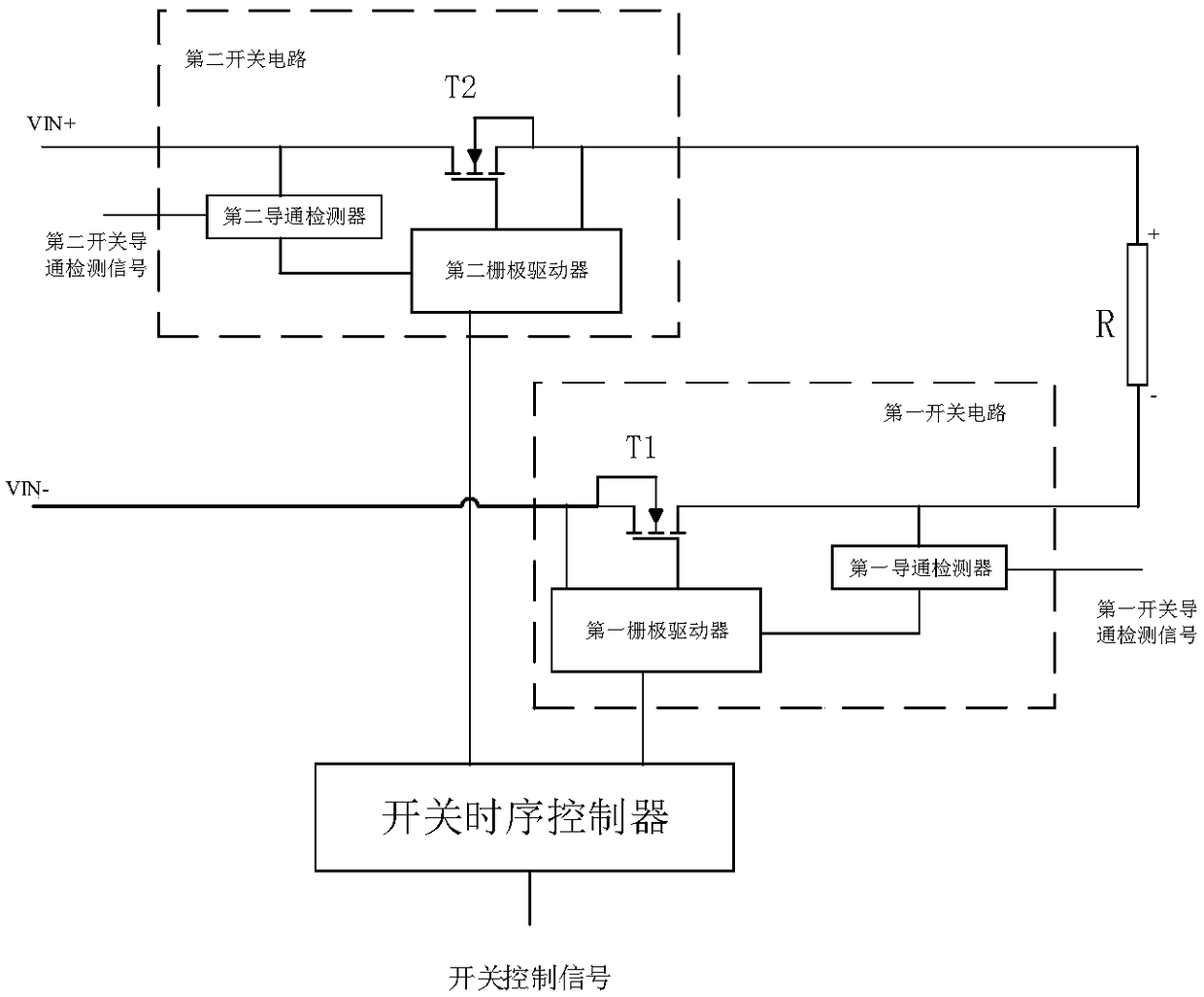
[0045] A specific embodiment of the present invention discloses a power electronic switch, specifically a miniature power electronic switch with self-detection function, such as figure 1 shown, including

[0046] The first switch circuit is connected between the negative pole of the power supply and the negative terminal of the load. Conduction detection signal;

[0047] The second switch circuit; connected between the positive pole of the power supply and the positive terminal of the load, under the control of the control signal, connects or disconnects the electrical connection between the positive pole of the power supply and the positive terminal o...


PUM


Abstract

The invention relates to a power electronic switch, comprising: a first switch circuit connected between the negative pole of a power source and the negative terminal of a load R, and a second switchcircuit connected between the positive pole of the power source and the positive terminal of the load R. The first switch circuit and the second switch circuit switch on or off the load R, and automatically detect whether a switch circuit is turned on. The power electronic switch realizes the on-off control of the power source, overcomes the disadvantages of the heavy weight, the large volume, thehigh price, the great influence on the electromagnetic environment in a product, and the short service life of a mechanical contact of an electromagnetic relay in a traditional power electronic switch, has a self-detection function to realizes the self-detection of a switch state.

Description

technical field [0001] The invention relates to the technical field of switches, in particular to a power electronic switch. Background technique [0002] At present, in the switching application of the power supply, the electromagnetic relay is the most commonly used switching device, but for the occasion with a large load current, the weight of the electromagnetic relay is heavy, the volume is large, and the price is relatively expensive, which directly affects the overall volume, weight and cost of the product. The cost, and the electromagnetic relay has a great impact on the electromagnetic environment in the product, and the life of the mechanical contact is low, which affects the stability and reliability of the system. [0003] In some applications, solid-state relays are used to realize power switches. Solid-state relays overcome the shortcomings of electromagnetic relays, such as heavy weight, large volume, great influence on the electromagnetic environment, and low...

Claims


Application Information

Patent Timeline
Patent Type & Authority Applications(China)
IPC IPC(8): H03K17/081H03K17/687
CPCH03K17/08104H03K17/687H03K2217/0081Y02B70/10
Inventor 白磊张志彦张浩坤郭光郭延磊周军
Owner BEIJING MECHANICAL EQUIP INST
Why Eureka
Try Eureka