
a microphone

A microphone and diaphragm technology, applied in the field of measurement, can solve the problems of unfavorable air circulation, reduce the mechanical sensitivity of the diaphragm, limit the high signal-to-noise ratio performance of the microphone, etc., and achieve the effect of high sensitivity and guaranteed performance.

Active Publication Date: 2020-05-12
WEIFANG GOERTEK MICROELECTRONICS CO LTD +1
View PDF7 Cites 0 Cited by
  • Summary
  • Abstract
  • Description
  • Claims
  • Application Information

AI Technical Summary

Problems solved by technology

This limits the design of the minimum package size of the MEMS microphone (>3mm 3 )
[0004] This is because if the volume of the rear cavity is too small, it is not conducive to the circulation of air, and the rigidity of this air will greatly reduce the mechanical sensitivity of the diaphragm
In addition, for pressure equalization, dense through-holes are usually designed on the back plate, and the air flow resistance in the gap or perforation caused by air viscosity becomes the dominant factor of MEMS microphone noise, thus limiting the high signal-to-noise ratio performance of the microphone

Method used


Image

  • a microphone
  • a microphone
  • a microphone

Examples


Embodiment 1

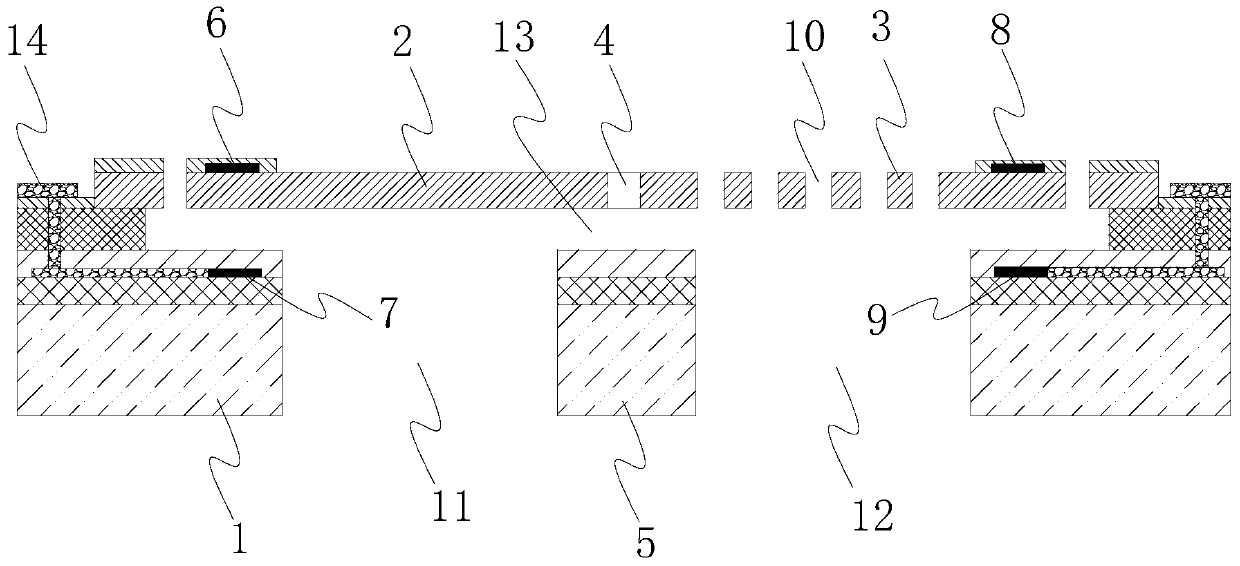
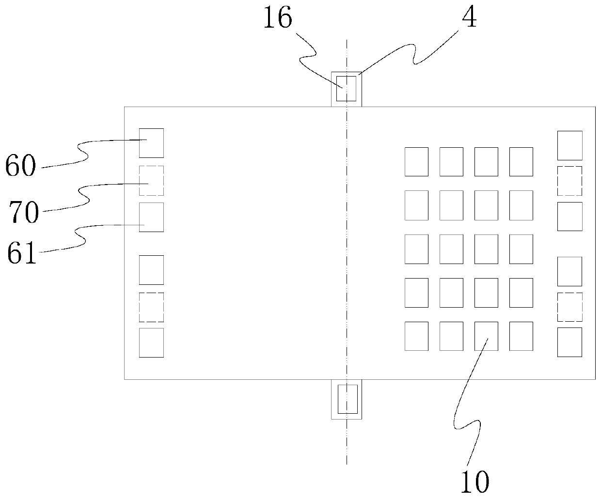
[0069] Specifically, refer to figure 2 , the first magnet 60 and the second magnet 61 are arranged on the first side 2 position of the diaphragm, the first magnet 60 and the second magnet 61 can adopt magnetic thin films, and the magnetic thin films can directly adopt magnetic materials, and can also be formed after forming the thin films. The film is magnetized. In a specific embodiment of the present invention, the magnetic thin film may be made of CoCrPt or CoPt.

[0070] The first magnet 60 and the second magnet 61 can be formed on the first side 2 of the diaphragm by deposition or other means known to those skilled in the art. The first magnet 60 and the second magnet 61 can also be protected by an insulating layer and a passivation layer, which will not be described in detail here.

[0071] The first magnet 60 and the second magnet 61 are arranged adjacent to each other, and are arranged horizontally on the first side 2 of the diaphragm sequentially in such a manner t...

Embodiment 2

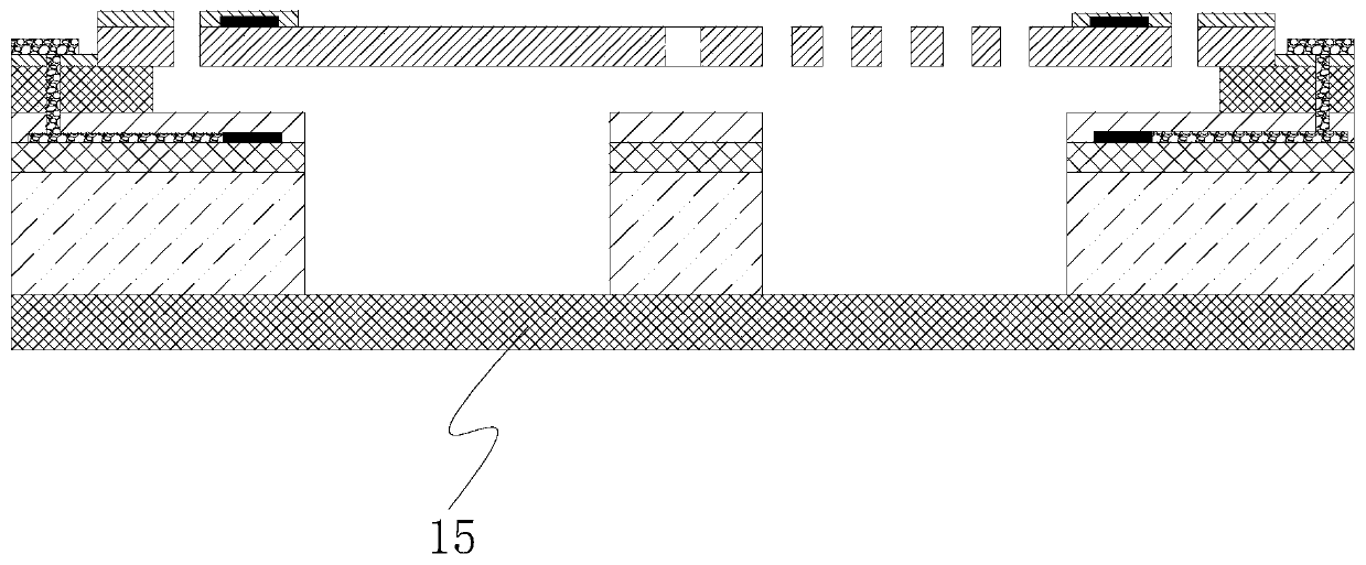
[0080] In a specific embodiment of the present invention, a bearing part 15 is also provided above the diaphragm, refer to Figure 5 . The carrying part 15 may be directly or indirectly connected to the substrate 1 through a spacer, and there is a certain gap between the carrying part 15 and the diaphragm, so that the carrying part 15 will not hinder the deflection of the diaphragm.

[0081] refer to Figure 5 , the first magnet 63 and the second magnet 62 of the first detection structure are respectively disposed on the substrate 1 and the bearing part 15 . The first magnet 63 and the second magnet 62 can use magnetic thin films, and the magnetic thin films can be directly made of magnetic materials, or the thin films can be magnetized after forming the thin films. In a specific embodiment of the present invention, the magnetic thin film may be made of CoCrPt or CoPt. In order to protect the magnets, the first magnet 63 and the second magnet 62 may respectively be provided...


PUM


Abstract

Disclosed in the present invention is a microphone. The middle position of a diaphragm plate is connected to a substrate by means of an elastic torsion beam to form a seesaw structure; the position of the second side of the diaphragm plate is provided with multiple spaces through which sound passes; the first side of and the second side of the diaphragm plate are respectively provided with a first detection structure and a second detection structure for representing deflection electrical signals at the corresponding sides of the diaphragm plate. The microphone of the present invention has high sensibility, the impact of the volume of a rear cavity on the microphone is low, the development of the microphone toward smaller thickness can be implemented, and the performance of the microphone can be ensured.

Description

technical field [0001] The invention relates to the field of measurement, more precisely, the invention relates to a microphone capable of realizing acoustic-electric conversion. Background technique [0002] The existing mainstream microphones are all capacitive microphones that are detected by the principle of a flat capacitor. In the structure of the microphone, the plate capacitor includes a substrate and a back plate and a diaphragm formed on the substrate. There is a gap between the back plate and the diaphragm, so that the back plate and the diaphragm form a flat plate. Capacitor sensing structure. [0003] In order to take full advantage of the mechanical sensitivity of the diaphragm, the microphone needs to be designed with a large back cavity with ambient pressure to ensure the rigidity of the flowing air far from the diaphragm. The volume of the dorsal cavity is usually much greater than 1mm 3 , such as usually designed for 1-15mm 3 . Moreover, when the micro...

Claims


Application Information

Patent Timeline
Patent Type & Authority Patents(China)
IPC IPC(8): H04R1/08
CPCH04R1/08
Inventor 邹泉波冷群文
Owner WEIFANG GOERTEK MICROELECTRONICS CO LTD
Learn More