High-pressure accumulator and method for producing a high-pressure accumulator

A storage and high-pressure technology, applied to fuel injection devices with oil storage, machines/engines, engine components, etc., can solve problems such as reducing component life

Inactive Publication Date: 2019-01-15
ROBERT BOSCH GMBH
View PDF12 Cites 2 Cited by
  • Summary
  • Abstract
  • Description
  • Claims
  • Application Information

AI Technical Summary

Problems solved by technology

[0004] Injection systems, especially high-pressure accumulators and injectors, are sensitive to pressure oscillations, which reduce the life of the components they are loaded on

Method used


Image

  • High-pressure accumulator and method for producing a high-pressure accumulator
  • High-pressure accumulator and method for producing a high-pressure accumulator
  • High-pressure accumulator and method for producing a high-pressure accumulator

Examples


Embodiment Construction

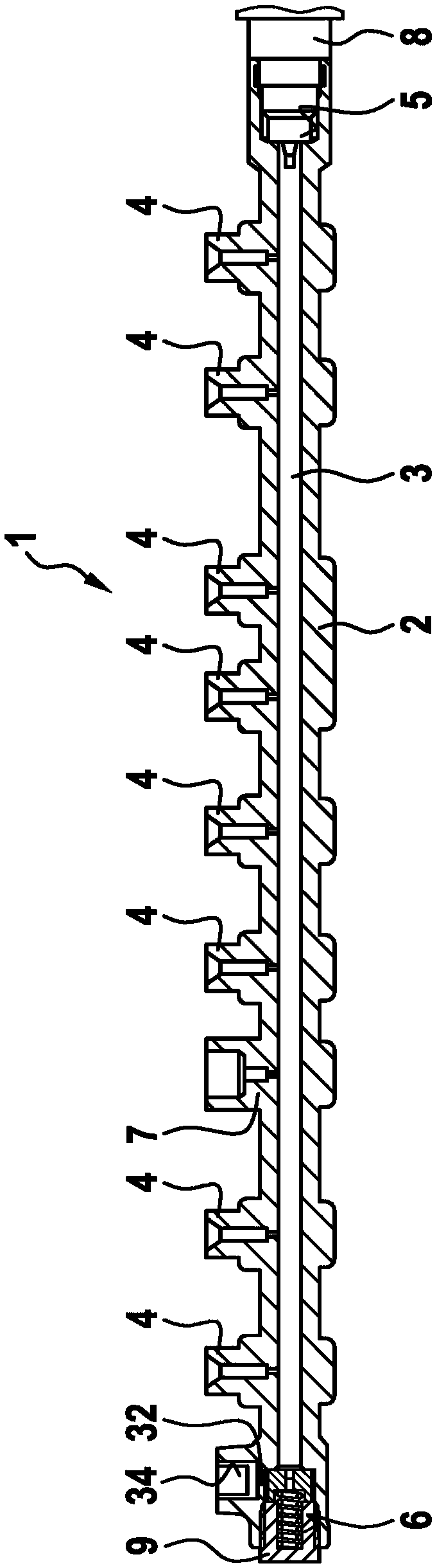
[0023] exist figure 1 In the longitudinal section of , a tubular high-pressure accumulator as known from the prior art is marked with 1 . The high-voltage store 1 has a store tube 2 which surrounds a store space 3 . The high-pressure accumulator 1 is provided for the injection system of the internal combustion engine and is usually referred to as a rail.

[0024] A plurality of outlet connections 4 for fuel pressure lines (not shown) to the injectors are formed on the accumulator line 2 of the high-pressure accumulator 1 . An inlet connection 7 to a high-pressure pump (not shown) is also formed on the accumulator tube 2 . In addition, receptacles 5 and 6 for attachment parts 8 and 9 are formed on the storage tube 2 . The attachment part 8 is usually a rail pressure sensor for ascertaining the pressure in the storage space 3 . The attachment part 9 is a pressure valve, preferably a pressure regulating valve for regulating the pressure in the storage space 3 . The pressure ...


PUM


Abstract

The invention relates to a high-pressure accumulator (1) for internal combustion engines for storing highly pressurized fuel. The high-pressure accumulator (1) comprises an accumulator pipe (2) with an accumulator chamber (3) formed in the accumulator pipe (2). The high-pressure accumulator (1) comprises a supply connection (7) for supplying highly pressurized fuel and at least one discharge connection (4) for discharging highly pressurized fuel. A honeycomb structure (10) is arranged in the accumulator chamber (3).

Description

technical field [0001] The invention relates to a high-pressure accumulator, in particular for an injection system of an internal combustion engine. Furthermore, the invention relates to a method for producing such a high-voltage store. Background technique [0002] TECHNICAL FIELD The present invention relates to a high-pressure accumulator, in particular for an injection system for injecting high-pressure fuel into a combustion chamber of an internal combustion engine, and to a method for producing such a high-pressure accumulator. [0003] High-voltage accumulators are known from the prior art, for example from DE 10 2008 040 901 A1. Known high-pressure accumulators have a storage space for storing high-pressure fuel. Furthermore, in addition to the pump-side and injector-side connections, there are also receptacles for attachment parts. Usually, two attachment parts, a rail pressure sensor and a pressure regulating valve or pressure limiting valve, are attached to the...

Claims


Application Information

Patent Timeline
Patent Type & Authority Applications(China)
IPC IPC(8): F02M55/02
CPCF02M55/025F02M2200/315F02M2200/80B33Y80/00F02M55/04F02M2200/40
Inventor D·乌尔曼G·费拉罗
Owner ROBERT BOSCH GMBH
Why Eureka
Try Eureka