Cleaning mechanism for filter

A cleaning mechanism and filter technology, applied in the direction of filter regeneration, filtration separation, chemical instruments and methods, etc., can solve the problems of increased cost, low efficiency, waste of manpower, etc., and achieve improved efficiency, convenient use, and simple structural design Effect

Inactive Publication Date: 2019-01-18
开平市富立润滑剂有限公司
View PDF0 Cites 2 Cited by
  • Summary
  • Abstract
  • Description
  • Claims
  • Application Information

AI Technical Summary

Problems solved by technology

Its efficiency is low, waste manpower, increase cost

Method used


Image

  • Cleaning mechanism for filter
  • Cleaning mechanism for filter
  • Cleaning mechanism for filter

Examples


Embodiment Construction

[0020] The best embodiment of the present invention will be further described in detail below.

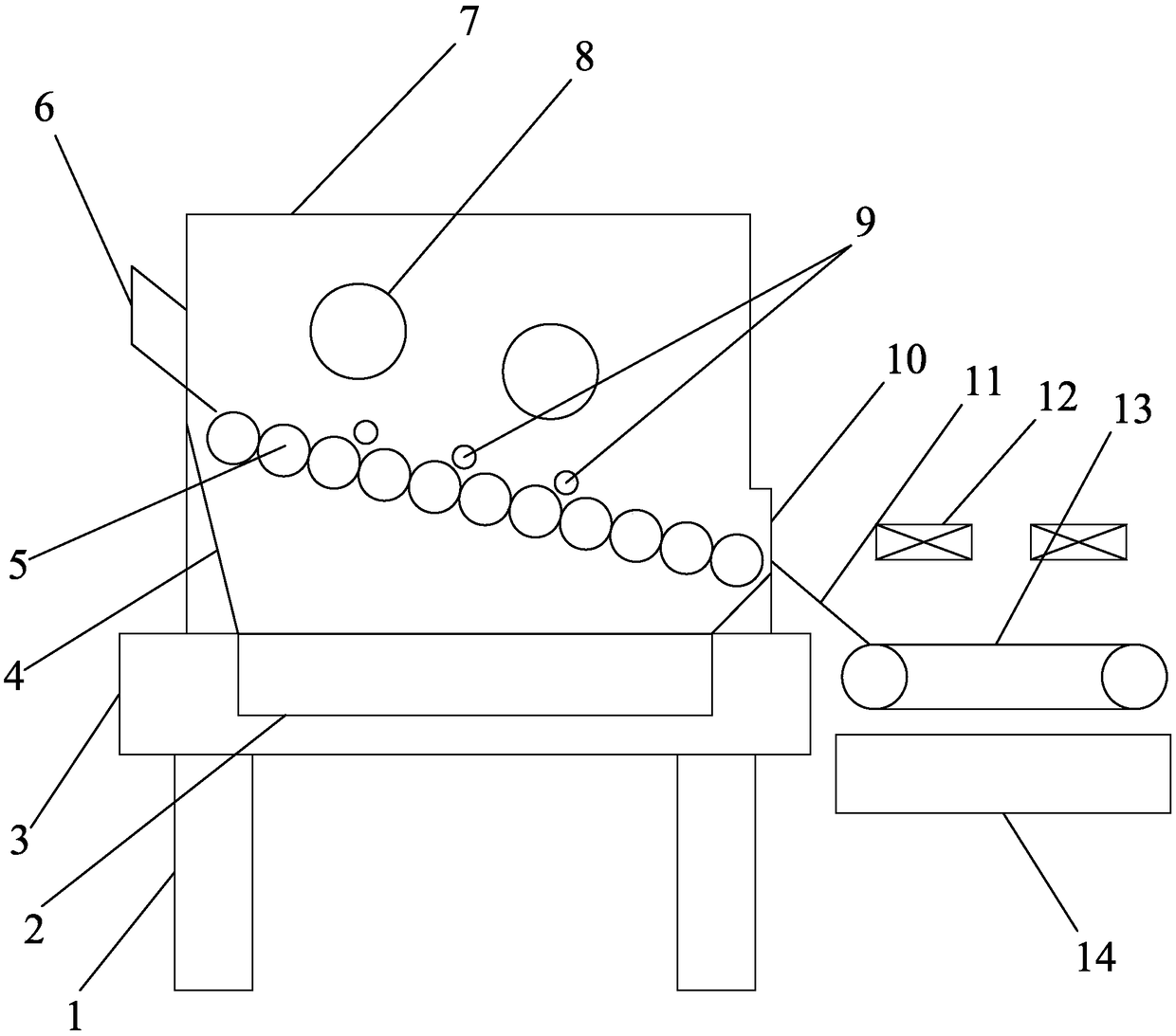
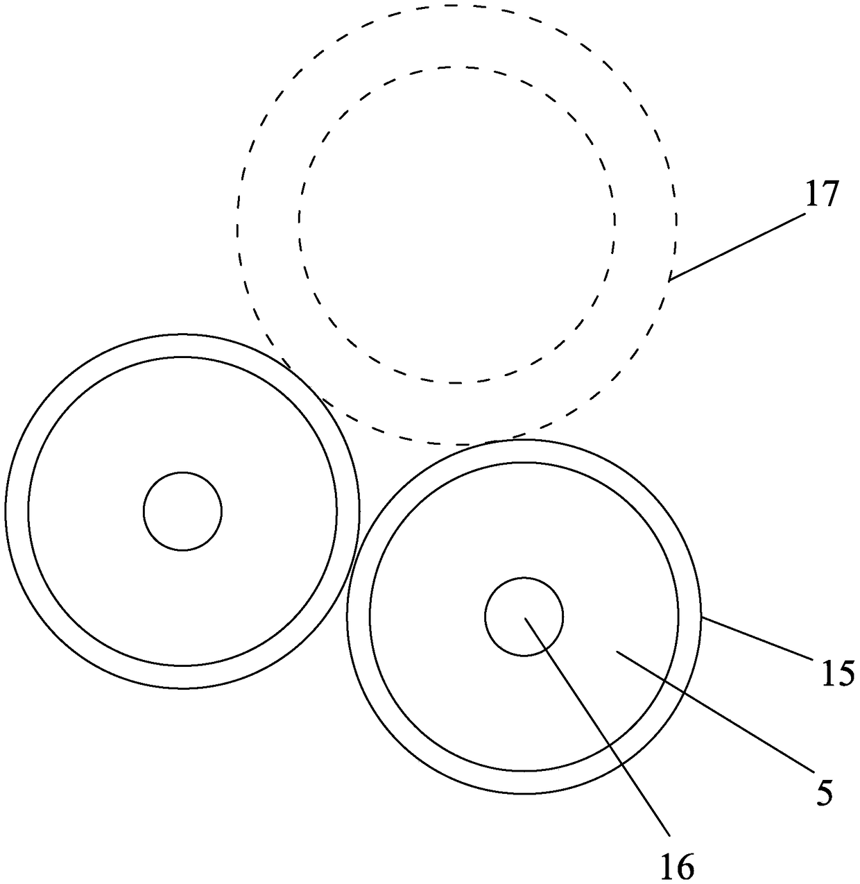
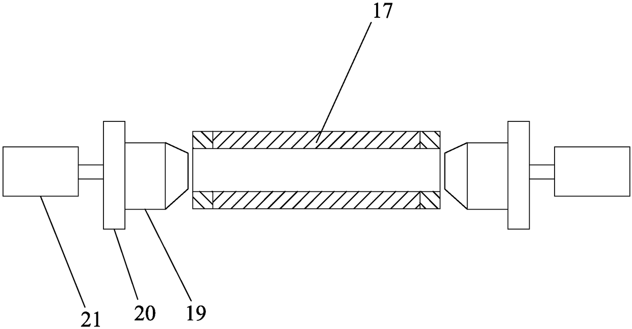
[0021] Such as Figure 1-4 As shown, in the embodiment of the present invention, the cleaning mechanism for the filter includes a bracket 1, a recovery box 2, a base 3, a front guide plate 4, a roller 5, an inlet 6, a cleaning box 7, a cleaning pipe 8, Flushing mechanism 9, outlet 10, guide plate 11, fan 12, conveying mesh belt 13, second recovery box 14, the base 3 is fixed on the upper end of the support 1, and the upper end of the base 3 is provided with a sealed cleaning box 8, the cleaning box 8 The left side is provided with inlet 6, and the right side of cleaning box 8 is provided with outlet 10. The rollers 5 are displaced downwards from the inlet 6 to the outlet 10, so that the cartridge filter 17 can roll down from the rollers 5; The type filter 17 sprays cleaning agent, and the plurality of rollers 7 are respectively provided with flushing mechanisms 9 opposite to each...


PUM


Abstract

The invention discloses a cleaning mechanism for a filter. The cleaning mechanism for the filter comprises a stand, a recycling box, a base, a front guiding plate, a plurality of roll shafts, an inlet, a cleaning box, a cleaning pipe, flushing mechanisms, an outlet, a guiding plate, a fan, a conveying net belt and a second recycling box, wherein the base is fixed to the upper end of the stand, thesealed cleaning box is arranged at the upper end of the base, the left side of the cleaning box is provided with the inlet, the right side of the cleaning box is provided with the outlet, the inlet is higher than the outlet, the multiple roll shafts arranged side by side are arranged in the cleaning box, the roll shafts are horizontally arranged, and the multiple roll shafts are sequentially staggered downwards from the inlet to the outlet; the cleaning pipe is arranged on the upper sides of the roll shafts, the flushing mechanisms arranged face to face are arranged at the positions, close totwo ends, of the roll shafts, the flushing mechanisms are connected with a detergent, and the flushing mechanisms are used for being inserted into the two ends of the cylinder type filter, and flushfrom the interior of the filter to the outer part; and the guiding plate is arranged on the outer side of the outlet, and the conveying net belt fixed to the stand is arranged at the tail end of the guiding plate. The cleaning mechanism can achieve automatic cleaning, saves manpower, lowers the cost and improves the efficiency.

Description

technical field [0001] The technical field of filter cleaning of the present invention particularly relates to a cleaning mechanism for filters. Background technique [0002] The filter (filter) is an indispensable device on the pipeline of the conveying medium, and is usually installed at the inlet end of the pressure reducing valve, pressure relief valve, constant water level valve, square filter and other equipment. The filter is composed of a cylinder, a stainless steel filter, a sewage discharge part, a transmission device and an electrical control part. After the water to be treated passes through the filter cartridge of the filter screen, its impurities are blocked. When cleaning is required, just take out the detachable filter cartridge and reinstall it after treatment. Therefore, the use and maintenance are extremely convenient. [0003] Cleaning agents are mostly used for filter cleaning. The traditional cleaning method uses manual operation, soaking the filter in...

Claims


Application Information

Patent Timeline
Patent Type & Authority Applications(China)
IPC IPC(8): B01D41/04
CPCB01D41/04
Inventor 何文立
Owner 开平市富立润滑剂有限公司
Why Eureka
Try Eureka