Electric riveting machine for bearing retainer

A technology of bearing cage and riveting machine, which is applied in the field of mechanical processing, can solve the problems of different sizes of rivet heads, poor consistency, and insufficient riveting, so as to improve production efficiency, solve poor consistency, and ensure stable effect

Pending Publication Date: 2019-01-18
HARBIN BEARING GROUP CORP
View PDF0 Cites 0 Cited by
  • Summary
  • Abstract
  • Description
  • Claims
  • Application Information

AI Technical Summary

Problems solved by technology

[0003] In order to solve the problem that the rivet of the existing bearing cage has poor consistency after riveting, the size of the rivet head is different, and the riveting is not in place, the invention further proposes an electric riveting machine for the bearing cage

Method used


Image

  • Electric riveting machine for bearing retainer
  • Electric riveting machine for bearing retainer

Examples


specific Embodiment approach 1

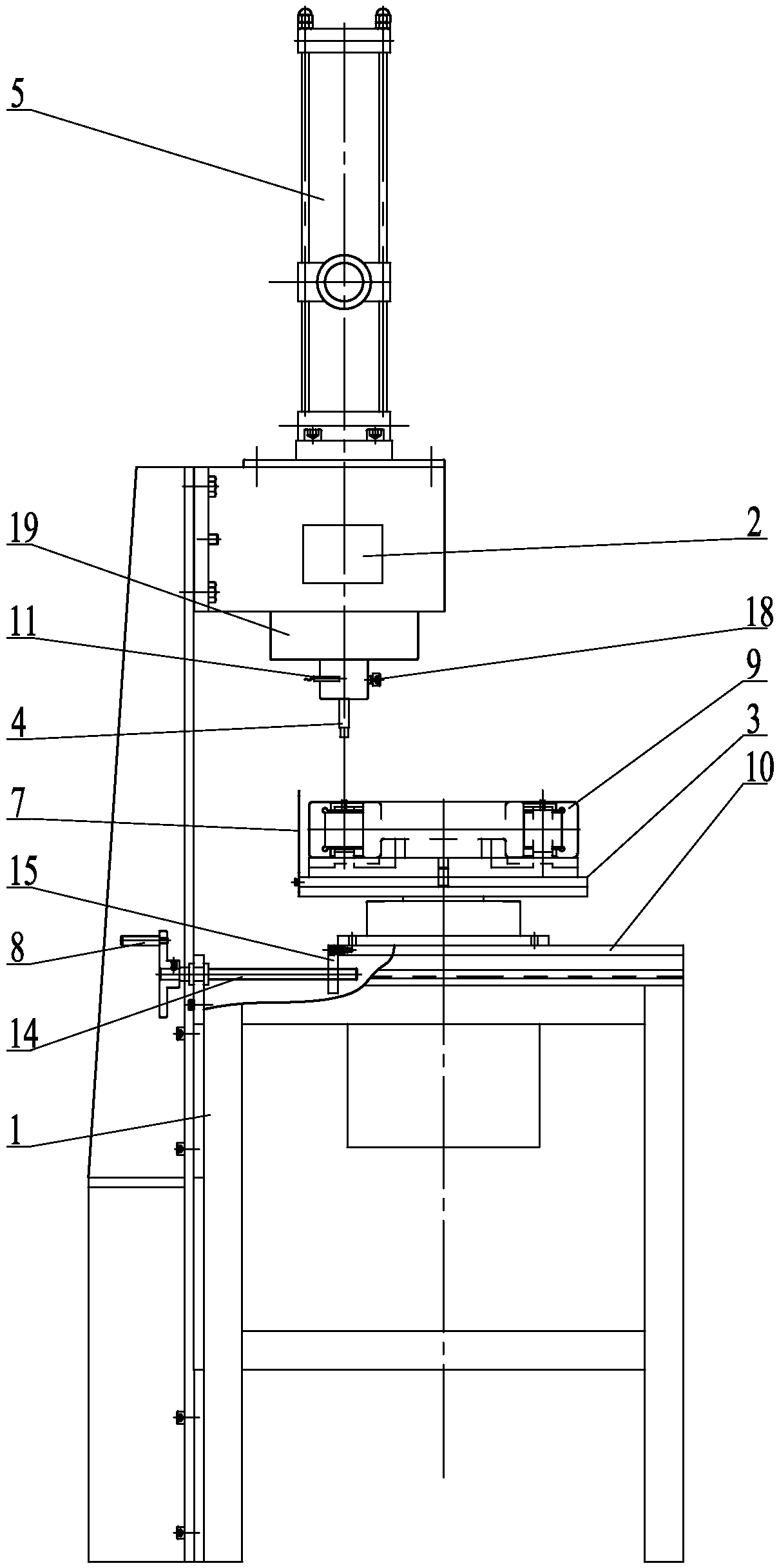
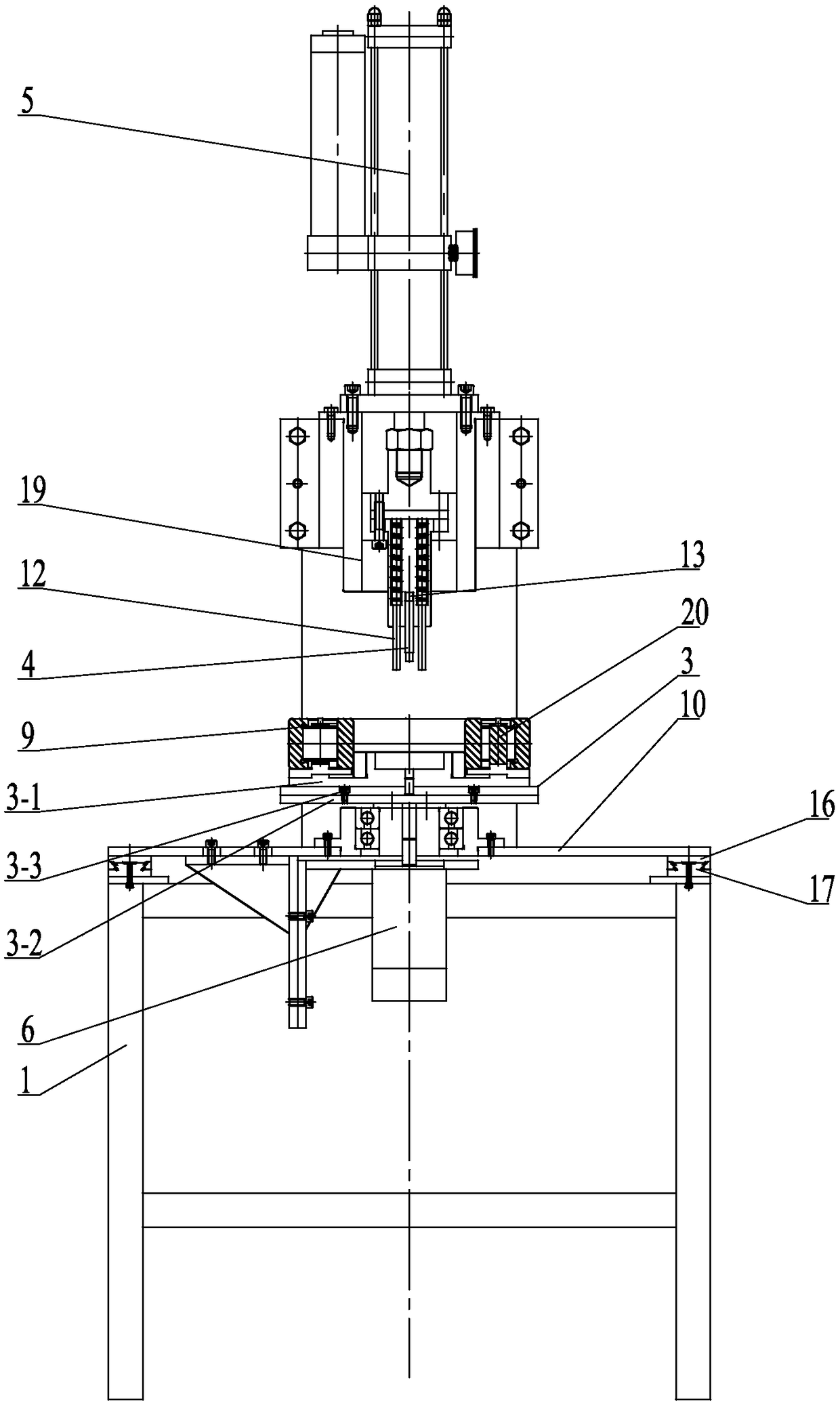
[0010] Specific implementation mode one: combine Figure 1 to Figure 2 Describe this embodiment, a bearing cage electric riveting machine described in this embodiment includes a frame 1, a controller 2, a bearing fixing seat 3, a riveting punch 4, a cylinder 5, a servo motor 6, a base 10, a heating 11 and a horizontal movement mechanism, the cylinder 5 is vertically arranged on the upper end of the frame 1, the riveting punch 4 is arranged at the end of the piston rod of the cylinder 5, the riveting punch 4 is provided with a heater 11, and the middle part of the frame 2 A base 10 is arranged horizontally, and the base 10 moves horizontally on the frame 2 through a horizontal moving mechanism. The upper end surface of the base 10 is provided with a bearing fixing seat 3, and the bearing fixing seat 3 is arranged at the lower end of the riveting punch 4, and the bearing The middle part of the fixed seat 3 is vertically fixed to the output shaft of the servo motor 6, and the cyl...

specific Embodiment approach 2

[0015] Specific implementation mode two: combination Figure 1 to Figure 2 The present embodiment is described. The pointer plate 7 is fixedly connected to one side of the bearing fixing seat 3 in the present embodiment. The undisclosed technical features in this embodiment are the same as those in the first embodiment.

[0016] The position of the pointer plate 7 designed in this way is the initial position when the servo motor 6 rotates. When placing the bearing 9 to be riveted, the first point to be riveted is directly facing the pointer plate 7, so as to successfully complete the subsequent riveting process.

specific Embodiment approach 3

[0017] Specific implementation mode three: combination Figure 1 to Figure 2 To illustrate this embodiment, a proximity switch sensor 12 is respectively provided on both sides of the riveting punch 4 in this embodiment, and the proximity switch sensor 12 is connected to the controller 2 . The undisclosed technical features in this embodiment are the same as those in the first or second specific embodiment.

[0018] Design in this way to realize the upward and downward control of the cylinder 5 piston rod by the proximity switch sensor 12 .


PUM


Abstract

The invention discloses an electric riveting machine for a bearing retainer and relates to the technical field of machining. The problems are solved that rivets of an existing bearing retainer after riveting are poor in consistency, the sizes of the rivet heads are different, and riveting is not in place. The electric riveting machine comprises a rack, a controller, a bearing fixing base, a riveting punch, an air cylinder, a servo motor, a base, a heater and a horizontal movement mechanism. The air cylinder is vertically arranged at the upper end of the rack, the riveting punch is arranged atthe tail end of a piston rod of the air cylinder, and the heater is arranged on the riveting punch; the base is horizontally arranged in the middle of the rack and moves on the rack in the horizontaldirection through the horizontal movement mechanism, the bearing fixing base is arranged on the upper end face of the base, and the bearing fixing base is arranged at the lower end of the riveting punch; the middle of the bearing fixing base is vertically and fixedly connected with an output shaft of the servo motor, and the air cylinder, the servo motor and the heater is connected with the controller separately. The electric riveting machine is used for bearing processing.

Description

technical field [0001] The invention relates to the technical field of machining, in particular to an electric riveting machine for a bearing cage. Background technique [0002] The existing large-scale cylindrical roller bearing cage riveting machine is in a semi-automatic state, requiring the operator to visually observe the heating temperature of the cage rivets, and rely on experience to determine the pressing time and pressing force. Rivets are riveted. Because the rivets of the bearing cage are riveted by manual operation equipment, the consistency of the rivet process after riveting is not good, and the size of the riveting head is different. Manual operation of the equipment for a long time makes some bearing cage rivets not riveted in place, which affects the quality of bearing products. Manually move the pressure bar, every time a rivet is riveted, the pressure bar needs to be manually moved once, and a bearing cage needs to be riveted with multiple rivets, which...

Claims


Application Information

Patent Timeline
Patent Type & Authority Applications(China)
IPC IPC(8): B21J15/14B21J15/18B21J15/26B21J15/30B21J15/38
CPCB21J15/14B21J15/18B21J15/26B21J15/30B21J15/38
Inventor 杨海峰孟祥国岳靖凯张昊晟
Owner HARBIN BEARING GROUP CORP
Why Eureka
Try Eureka