
Polishing machine tool and fixture thereof

A fixture and machine tool technology, which is applied in the field of processing machine tools, can solve the problems of unguaranteed placement accuracy, cumbersome process, and low precision, and achieve the effects of solving different workpiece polishing accuracy, simple device structure, and improving work efficiency

Inactive Publication Date: 2019-01-18
GUANGDONG UNIV OF TECH
View PDF5 Cites 5 Cited by
  • Summary
  • Abstract
  • Description
  • Claims
  • Application Information

AI Technical Summary

Problems solved by technology

[0003] In the traditional processing of optical components, it is mainly completed by manual operation or ordinary fixture clamping equipment, which will not only increase the cost and slow down the production efficiency, but more importantly, the accuracy of placement cannot be guaranteed, mainly because The coaxiality between the rotating shaft and the workpiece cannot be maintained by manual operation or clamping by ordinary fixtures, resulting in the inconsistent surface polishing degree of the polished workpiece with the set parameters, and waste products are prone to occur
That is, through manual adjustment, and then through dial gauge detection, the operator has high technical requirements, takes a long time, the process is cumbersome, and the accuracy is not high
Coaxial alignment is achieved through ordinary fixtures, which are affected by the accuracy of the fixture itself, and cannot be fine-tuned, and the effect of coaxial alignment cannot be determined

Method used


Image

  • Polishing machine tool and fixture thereof
  • Polishing machine tool and fixture thereof

Examples


Embodiment Construction

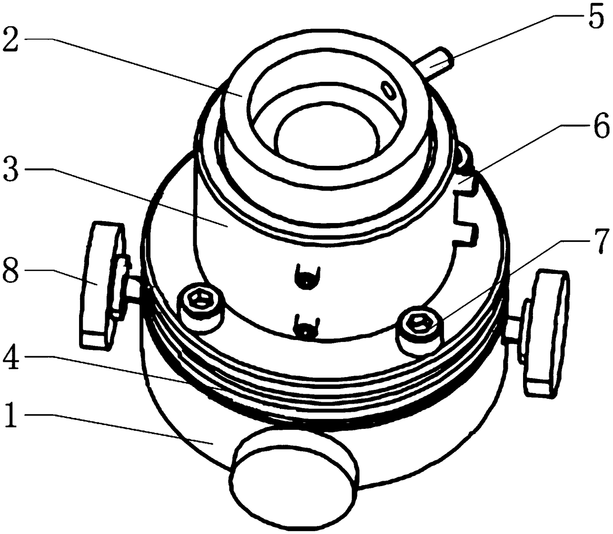
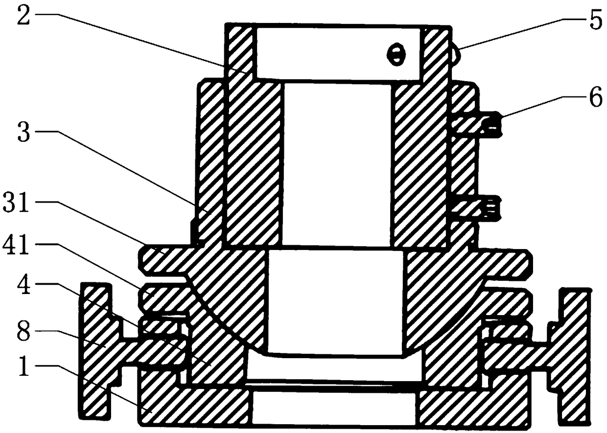
[0021] The core of the present invention is to provide a fixture for a polishing machine tool. The angle between the workpiece and the vertical direction can be adjusted through the angle adjustment device, so that the workpiece and the rotating shaft can be placed coaxially, fine-tuning can be performed, and the positioning accuracy is good. Another core of the present invention is to provide a polishing machine tool including the above fixture.

[0022] In order to enable those skilled in the art to better understand the solution of the present invention, the present invention will be further described in detail below in conjunction with the accompanying drawings and specific embodiments.

[0023] Please refer to figure 1 and figure 2 , figure 1 It is a structural schematic diagram of a specific embodiment of the clamp provided by the present invention; figure 2 It is a schematic cross-sectional view of a specific embodiment of the clamp provided by the present inventio...


PUM


Abstract

The invention discloses a fixture of a polishing machine tool, which comprises a base used for being sleeved and connected with the end part of a rotating shaft of the polishing machine tool, a work piece shaft sleeve used for clamping the end part of a work piece to be polished and an angle adjusting device, wherein the upper end of the angle adjusting device is connected with the work piece shaft sleeve, the lower end of the angle adjusting device is connected with the base, and the upper end of the adjusting device can swing relative to the lower end so as to adjust the included angle between the shaft sleeve of the work piece and the vertical direction. The working efficiency is improved, fine adjustment can be carried out, the device has a simple structure, the manufacturing cost is low, the use is convenient, position correction is carried out while the work piece is fixed, the product quality is high, the use effect is good, the stable consistency of the processing quality of work pieces is ensured, the problems of different work piece polishing precision and high rejection rate caused by prior manual operation polishing equipment are solved. The invention also discloses a polishing machine tool comprising the fixture.

Description

technical field [0001] The invention relates to the field of processing machine tools, in particular to a fixture of a polishing machine tool. In addition, the present invention also relates to a polishing machine tool comprising the above fixture. Background technique [0002] At present, all kinds of optical systems play an irreplaceable role in military and civilian fields, and the increasingly prominent important role makes the optical system have higher and higher requirements for the accuracy of optical components. In the field of ultra-precision machining, the workpiece to be polished is placed on the rotating shaft, and the rotating shaft drives the workpiece to rotate for polishing. Therefore, placing the workpiece coaxially with the rotating shaft is an important processing procedure, and its coaxial accuracy will seriously affect the optical quality of the polished workpiece. performance. [0003] In the traditional processing of optical components, it is mainly...

Claims


Application Information

Patent Timeline
IPC IPC(8): B24B13/005B24B13/00
CPCB24B13/00B24B13/0055
Inventor 黄松明姚洪辉王晗邱汉卓少木辛正旭李年丰张嘉荣
Owner GUANGDONG UNIV OF TECH
Learn More