[0033] The technical solutions of the present invention will be clearly and completely described below in conjunction with the accompanying drawings. Obviously, the described embodiments are part of the embodiments of the present invention, rather than all of them. Based on the embodiments of the present invention, all other embodiments obtained by those of ordinary skill in the art without creative work shall fall within the protection scope of the present invention.
[0034] In the description of the present invention, it should be noted that the terms "center", "upper", "lower", "left", "right", "vertical", "horizontal", "inner", "outer", etc. The indicated orientation or positional relationship is based on the orientation or positional relationship shown in the drawings, and is only for the convenience of describing the present invention and simplifying the description, rather than indicating or implying that the pointed device or element must have a specific orientation or a specific orientation. The structure and operation cannot therefore be understood as a limitation of the present invention. In addition, the terms "first", "second", and "third" are only used for descriptive purposes, and cannot be understood as indicating or implying relative importance.
[0035] In the description of the present invention, it should be noted that the terms "installation", "connected" and "connected" should be understood in a broad sense, unless otherwise clearly specified and limited. For example, they can be fixed or detachable. Connected or integrally connected; it can be a mechanical connection or an electrical connection; it can be directly connected or indirectly connected through an intermediate medium, and it can be the internal communication between two components. For those of ordinary skill in the art, the specific meanings of the above-mentioned terms in the present invention can be understood in specific situations.
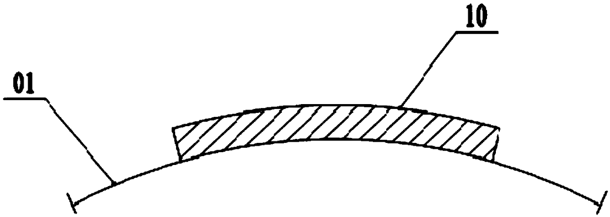
[0036] The bilge keel 10 in the prior art generally determines the width of the bilge keel 10 based on the principle of not touching the bottom or touching the wall. Please refer to figure 1 , The bilge keel 10 is along the length of the hull 01, and the width is equal everywhere.
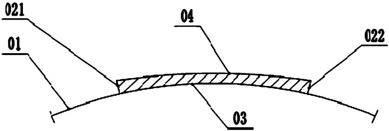
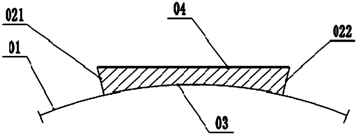
[0037] The first aspect of the present invention provides a variable width bilge keel. The variable width bilge keel provided by the present invention includes: a keel plate 02; the keel plate 02 includes a first contour edge 03 and a second contour edge 04, and the first contour edge 03 It is used to fit the side of the hull 01 and extend along the length of the hull 01; the second silhouette edge 04 is opposite to the first silhouette edge 03; the first silhouette edge 03 and the first silhouette edge 03 along the normal direction of the first silhouette edge 03 The distance between the two silhouette edges 04 gradually increases from the middle of the first silhouette edge 03 to both ends.
[0038] Specifically, the variable width bilge keel provided by the present invention is installed on the side of the hull 01, and the first contour edge 03 is attached to the side of the hull 01. In a ship in the prior art, in order to reduce the water flow resistance and navigation stability during navigation, the sides of the hull 01 generally bulge outward. The first contour edge 03 is recessed toward the second contour edge 04 and fits the side of the hull 01.
[0039] The variable width bilge keel provided by the present invention, due to the distance between the first contour edge 03 and the second contour edge 04 along the normal direction of the first contour edge 03, from the middle of the first contour edge 03 to both ends, Respectively increase gradually, so that the width of the keel plate 02 gradually increases from the middle to the bow and from the middle to the stern. In this way, the side surface of the hull 01 is convex outwards, the middle width is large, and the first contour edge 03 is recessed along the side of the hull 01, so that the keel can be enlarged without increasing the overall width of the hull 01. The area of the board 02.
[0040] The variable width bilge keel provided by the present invention increases the area of the keel plate 02, can increase the additional water resistance to the ship's rolling during the ship's navigation, helps improve the ship's rolling condition, and enhances the slowing down of the ship's rolling Effect; Moreover, the overall width of the hull 01 has not increased, and the risk of the ship touching the wall from the bottom is effectively controlled.
[0041] In some embodiments, the first silhouette edge 03 is a circular arc curve.
[0042] In some embodiments, the first silhouette edge 03 includes a straight line segment. The normal line of the first contour edge 03 of the straight line segment refers to the straight line perpendicular to the straight line segment.
[0043] Further, the keel plate 02 includes a bow end 021 and a stern end 022, the bow end 021 is close to the bow of the hull 01, and the stern end 022 is close to the stern of the hull 01; the keel plate 02 is integrated from the bow end 021 to the stern end 022 structure.
[0044] Specifically, please refer to Figure 2-Figure 4 , The keel plate 02 is installed on the side of the hull 01 and extends along the length of the hull 01, which is beneficial to provide a larger surface area to generate a larger additional water resistance to prevent the ship from rolling, and to improve the seakeeping of the ship.
[0045] Further, the second contour edge 04 is convex in a direction away from the first contour edge 03.
[0046] Specifically, the second contour edge 04 is a curve and is convex in a direction away from the first contour edge 03, so that the width of the keel plate 02 gradually increases from the middle to the two ends of the keel plate 02.
[0047] The width of the keel plate 02 refers to the distance between the first contour edge 03 and the second contour edge 04 along the normal direction of the first contour edge 03.
[0048] Further, the second silhouette edge 04 includes the bow section 041 and the stern section 042. The bow section 041 is connected to the stern section 042; the normal line of the first silhouette edge 03 and the bow section 041 at the intersection of the bow section 041 The tangent line, relative to the tangent line of the first silhouette edge 03 at this point, slopes away from the first silhouette edge 03 in the direction pointing to the bow end 021; the normal line of the first silhouette edge 03 is the same as that of the bow section 041 The tangent line of the stern section 042 at the intersection point, relative to the tangent line of the first silhouette edge 03 at this point, is inclined in a direction pointing to the stern end 022 to a direction away from the first silhouette edge 03.
[0049] Specifically, the normal line of the first silhouette edge 03 intersects the first silhouette edge 03 and the bow section 041 respectively, and the tangent line at the intersection point of the bow section 041 is inclined with respect to the tangent line at the intersection point of the first silhouette edge 03 to achieve The width between the bow section 041 and the first silhouette side 03 gradually increases in the direction toward the bow end 021.
[0050] The normal line of the first silhouette edge 03 intersects the first silhouette edge 03 and the stern section 042 respectively. The tangent at the intersection point of the stern section 042 is inclined with respect to the tangent line at the intersection point of the first silhouette edge 03 to realize the stern section 042 and the stern section 042. The width between a silhouette edge 03 gradually increases in the direction toward the stern end 022.
[0051] In some embodiments, please refer to Figure 4 , The second silhouette edge 04 also includes a middle section 043, the two ends of the middle section 043 are respectively connected with the bow section 041 and the stern section 042.
[0052] In some embodiments, the middle section 043 is convex in a direction away from the first contour edge 03; from the middle of the middle section 043 to both ends, the width between the first contour edge 03 and the middle section 043 gradually increases.
[0053] The middle section 043 corresponds to the middle of the hull 01 with the widest width. The tangent line at a point on the middle section 043 is perpendicular to the width direction of the hull 01; the second contour edge 04 is located between the tangent and the first contour edge 03. In this way, the overall width of the hull 01 may not be increased.
[0054] As another embodiment, the middle section 043 extends along a straight line, and the middle section 043 is perpendicular to the width direction of the hull 01. The second contour edge 04 is located between the extension line of the middle section 043 and the first contour edge 03, so as not to increase the overall width of the hull 01.
[0055] As another embodiment, the tangent line of the bow section 041 at the intersection of the normal line of the first silhouette edge 03 and the bow section 041, relative to the tangent line of the first silhouette edge 03 at this point, points to the bow end The direction of 021 is inclined away from the first silhouette edge 03; the stern section 042 extends along a straight line and is perpendicular to the width direction of the hull 01.
[0056] As another embodiment, the tangent line of the stern section 042 at the intersection of the normal line of the first silhouette edge 03 and the stern section 042 is in a direction pointing to the stern end 022 relative to the tangent line of the first silhouette edge 03 at this point. Incline to the direction away from the first silhouette edge 03; the bow section 041 extends along a straight line and is perpendicular to the width direction of the hull 01.
[0057] Further, the radius of curvature of the first contour edge 03 at the intersection of the normal of the first contour edge 03 and the first contour edge 03 is smaller than the second contour at the intersection of the normal of the first contour edge 03 and the second contour edge 04 The radius of curvature of side 04.
[0058] Specifically, the first contour edge 03 and the second contour edge 04 are both curved and convex to the same side; the first contour edge 03 is located on the concave side of the second contour edge 04. The radius of curvature of the first contour edge 03 is smaller than that of the second contour edge 04, that is, the curvature of the first contour edge 03 is greater than that of the second contour edge 04, so that the first contour edge 03 and the second contour edge 04 are The distance between them gradually increases from the middle to the ends.
[0059] As another embodiment, the second contour edge 04 extends in a straight line from the bow end 021 to the stern end 022. The second silhouette edge 04 is perpendicular to the width direction of the hull 01 so as not to increase the overall width of the hull 01 and maximize the surface area of the keel plate 02.
[0060] As another embodiment, the second contour edge 04 includes a first straight line segment and a second straight line segment, one end of the first straight line segment is connected to one end of the second straight line segment; the first straight line segment extends toward the bow end 021, The two straight sections extend towards the stern end 022. In addition, the first straight line section is inclined toward the first silhouette side 03 in the direction pointing to the bow end 021; the second straight line section is inclined toward the first silhouette side 03 in the direction pointing to the stern end 022.
[0061] Further, the keel plate 02 includes a plurality of keel sub-boards 06, and the multiple keel sub-boards 06 are distributed at intervals from the bow to the stern of the hull 01.
[0062] Specifically, please refer to Figure 5 , The second contour edge 04 of each keel sub-board 06 is connected with the hull 01. The keel plate 02 is composed of multiple keel sub-plates 06, which can be installed to the hull 01 respectively. Compared with the method of installing the keel plate 02 to the hull 01 as a whole, the installation is more convenient and the assembly difficulty of the keel plate 02 is reduced. .
[0063] Furthermore, the variable-width bilge keel provided by the present invention further includes a mounting plate 05. The first contour edge 03 of the keel plate 02 is connected to the mounting plate 05; the keel plate 02 is connected to the hull 01 through the mounting plate 05.
[0064] Specifically, the second contour edges 04 of the multiple keel dividing plates 06 are all connected to one side surface of the mounting plate 05, and the other side surface of the mounting plate 05 is used to fit with the side surface of the hull 01. The mounting plate 05 can be welded to the hull 01 or fixed to the hull 01 by bolts.
[0065] The second aspect of the present invention provides a ship. The ship provided by the present invention includes a hull 01 and two groups of variable width bilge keels described above, and the two groups of variable width bilge keels are respectively connected to both sides of the hull 01.
[0066] Specifically, the variable-width bilge keels located on both sides of the hull 01 provide additional water resistance to prevent the ship from rolling during the ship's navigation, so as to reduce the ship's rolling and improve the ship's seakeeping.
[0067] In some embodiments, two sets of variable width bilge keels are symmetrically arranged on both sides of the hull 01.
[0068] Further, the bilge keel with variable width is welded to the hull 01.
[0069] As another embodiment, the ship provided by the present invention further includes a locking mechanism; the variable-width bilge keel is rotatably connected to the hull 01, the variable-width bilge keel can be rotated relative to the hull 01, and the axis of rotation is parallel to the length of the hull 01 Direction; the locking mechanism is used to lock the variable width bilge keel and the hull 01.
[0070] By adjusting the inclination angle of the variable-width bilge keel relative to the hull 01, the overall width and anti-rolling performance of the ship provided by the present invention can be adjusted, which is beneficial to adapt to different waters.
[0071] Specifically, please refer to Image 6 with Figure 7 , The side of the hull 01 is provided with a fixed seat 07, the fixed seat 07 is provided with a circular hole, and the axis of the circular hole is along the length direction of the hull 01; the end of the variable-width bilge keel is provided with a rotating shaft 08 that matches the circular hole. 08 is inserted into the circular hole; the bilge keel with variable width can rotate around the axis of the circular hole relative to the fixed seat 07.
[0072] The fixing seat 07 is provided with a threaded through hole; the locking mechanism includes a locking screw 09. The locking screw 09 cooperates with the threaded through hole and abuts against the bilge keel of variable width, so as to lock the bilge keel of variable width and the fixed seat 07.
[0073] Finally, it should be noted that the various embodiments in this specification are described in a progressive manner, and each embodiment focuses on the differences from other embodiments. For the same and similar parts between the various embodiments, refer to each other. That is, the above embodiments are only used to illustrate the technical solutions of the present invention, but not to limit it; although the present invention has been described in detail with reference to the foregoing embodiments, those of ordinary skill in the art should understand that: The technical solutions described in the foregoing embodiments are modified, or some or all of the technical features are equivalently replaced; the embodiments in the application and the features in the embodiments can be combined with each other if there is no conflict. However, these modifications, substitutions or combinations do not make the essence of the corresponding technical solutions deviate from the scope of the technical solutions of the embodiments of the present invention.