
Piston shoe and plunger assembly and plunger pump

A plunger pump and plunger technology, applied in the direction of pumps, multi-cylinder pumps, pump components, etc., can solve the problems of long service life, difficulty in meeting high working pressure, and easy damage to sliding shoe plunger components

Inactive Publication Date: 2019-01-18
SICHUAN AEROSPACE FENGHUO SERVO CONTROL TECH CO LTD
View PDF4 Cites 4 Cited by
  • Summary
  • Abstract
  • Description
  • Claims
  • Application Information

AI Technical Summary

Problems solved by technology

[0005] In view of this, the first object of the present invention is to provide a sliding shoe plunger assembly, the structural design of which can effectively solve the problem that the sliding shoe plunger assembly in the plunger pump is easily damaged and difficult to meet the high working pressure. and long service life requirements, etc., the second object of the present invention is to provide a plunger pump comprising the above-mentioned slipper plunger assembly

Method used


Image

  • Piston shoe and plunger assembly and plunger pump
  • Piston shoe and plunger assembly and plunger pump
  • Piston shoe and plunger assembly and plunger pump

Examples


Embodiment Construction

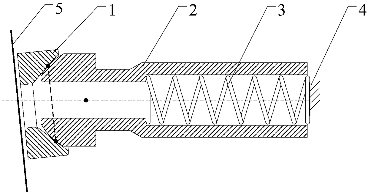
[0020] The embodiment of the invention discloses a sliding shoe plunger assembly to solve the technical problems that the sliding shoe plunger assembly in a plunger pump is easily damaged and difficult to meet the requirements of high working pressure and long service life.

[0021] The following will clearly and completely describe the technical solutions in the embodiments of the present invention with reference to the accompanying drawings in the embodiments of the present invention. Obviously, the described embodiments are only some, not all, embodiments of the present invention. Based on the embodiments of the present invention, all other embodiments obtained by persons of ordinary skill in the art without making creative efforts belong to the protection scope of the present invention.

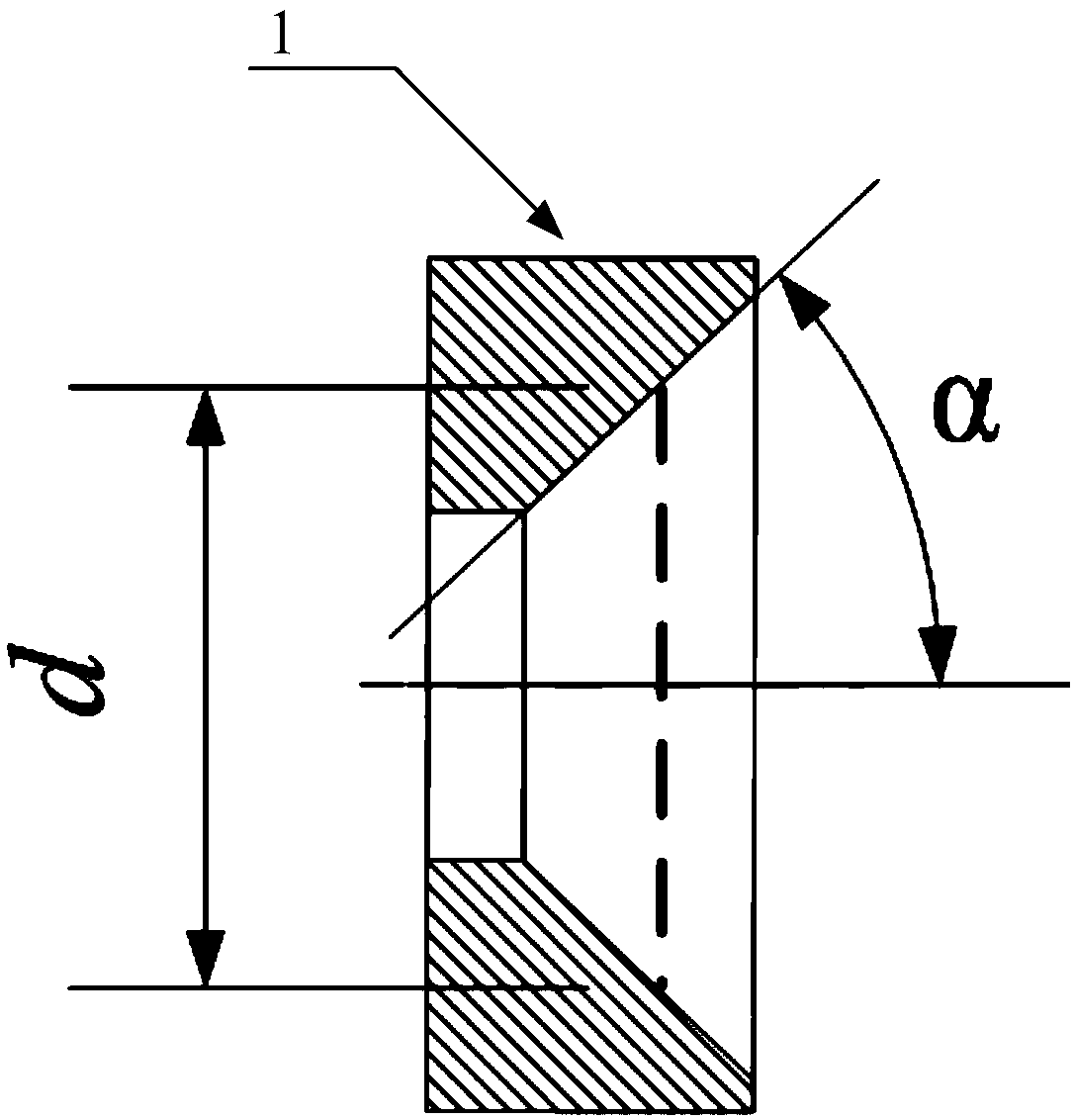
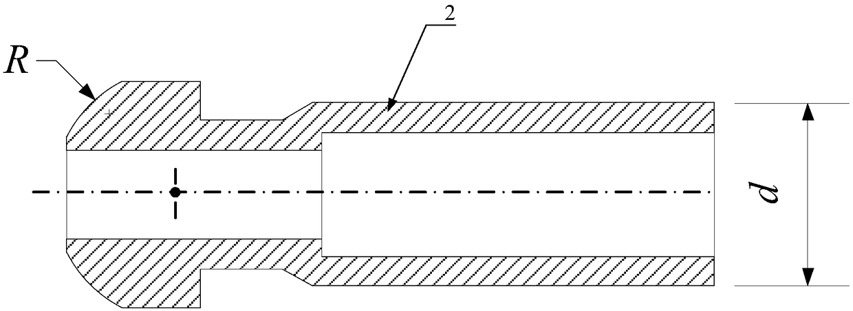
[0022] see Figure 1-Figure 3 , figure 1 Schematic diagram of the structure of the sliding shoe plunger assembly provided by the embodiment of the present invention; figure 2 Schematic...


PUM


Abstract

The invention discloses a piston shoe and plunger assembly which comprises a piston shoe and a plunger. The piston shoe is used for being connected with a plunger end and being in sliding fit with aninclined plate of a plunger pump. A columnar cavity running through the plunger axially is formed in the plunger. A concave circular conical surface structure is arranged on the end, used for being connected with the plunger, of the piston shoe, a protruding local spherical structure is arranged at one end of the plunger, and line-surface contact sealing fit is realized between the circular conical surface structure and the local spherical structure. The conical surface is adopted for the piston shoe, the spherical design is adopted for the plunger end, the piston shoe and the plunger end fitand abut under the effect of a spring to form circular linear fit, fluid pressures on the two sides of a sealing line are communicated through the plunger cavity, the high-pressure acting force at thetwo ends of the plunger counteract, and the loads acting on the plunger end by the piston shoe are reduced; equivalently, the piston is only used as a sealing element for changing the volume of an oil cavity, the original needed axial bearing is reduced, a direct bearing piece is replaced with the inclined plate, the bearing value of the plunger and the piston shoe is greatly reduced, and therefore the piston shoe and plunger assembly is higher in wear resistance and longer in service life. The invention further discloses the plunger pump.

Description

technical field [0001] The present invention relates to the technical field of plunger pump design, more specifically, to a slipper plunger assembly, and also to a plunger pump. Background technique [0002] High-pressure, high-speed, long-life and low-cost hydraulic pumps are an important development direction of hydraulic components at present and in the future. As the pressure increases, the wear is serious and the life is short, which seriously restricts the development of hydraulic pumps in the direction of high pressure and long life. [0003] In the existing sliding shoe plunger assembly technology, the main function of the swash plate in the plunger pump or the eccentric crankshaft in the radial piston pump is to provide reciprocating linear motion for the plunger, and the swash plate, shoe and plunger are the main Among them, the design of the sliding shoe is mainly based on the static pressure support principle of the residual pressing force, and the use of new we...

Claims


Application Information

Patent Timeline
IPC IPC(8): F04B1/12F04B53/00
CPCF04B1/122F04B1/124F04B1/126
Inventor 陈君辉尹大禹李侃司国雷朱旭邓熠潘游
Owner SICHUAN AEROSPACE FENGHUO SERVO CONTROL TECH CO LTD
Learn More