Oil-gas separator

A technology of oil-gas separator and separator, which is applied in the direction of separation method, dispersed particle separation, machine/engine, etc., which can solve the problems of oil-gas separator layout influence, vehicle modification space compression, etc., to reduce the difficulty of design and modification and installation height The effect of reducing requirements and good separation effect

Pending Publication Date: 2019-01-18
NANJING AEROSUN MORITA ENVIRONMENTAL PROTECTION S&T
View PDF0 Cites 5 Cited by
  • Summary
  • Abstract
  • Description
  • Claims
  • Application Information

AI Technical Summary

Problems solved by technology

With the upgrade of sanitation vehicle chassis emission standards, chassis exhaust gas treatment equipment is also gradually increasing, resulting in the compression of vehicle modification space, and the layout of large or multiple oil-gas separators will be affected to a certain extent

Method used


Image

  • Oil-gas separator
  • Oil-gas separator
  • Oil-gas separator

Examples


Embodiment

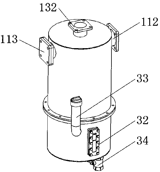
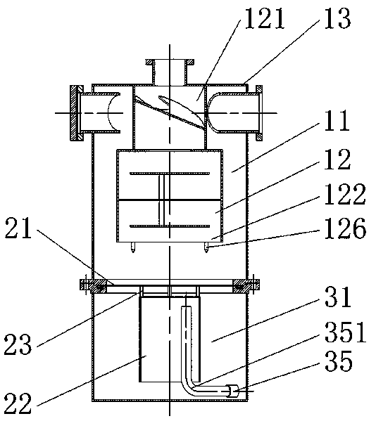
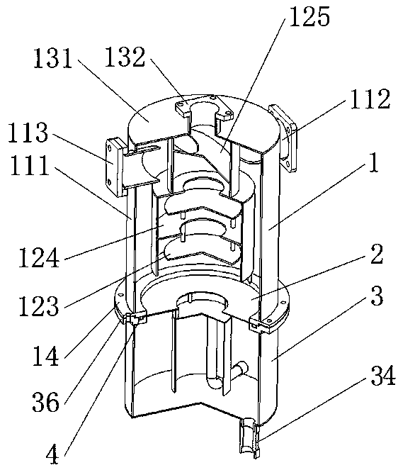
[0023] The oil-gas separator of the present embodiment, as figure 1 , figure 2 and image 3 As shown, it includes: a separator main body 1, an isolation disc 2 and an oil storage cylinder 3 arranged in sequence from top to bottom.

[0024] The separator main body 1 includes an outer cylinder 11, an inner cylinder 12 arranged in the outer cylinder 11, an upper cover 13 covering the tops of the outer cylinder 11 and the inner cylinder 12, and an upper connecting plate 14 arranged at the bottom of the outer cylinder 11, the outer cylinder 11 and the inner cylinder 12 is connected by an upper cover 13, and the inner cylinder 12 is arranged coaxially with the outer cylinder 11; two air intake pipes 112 are arranged symmetrically on the upper side of the outer cylinder 11, one of which is covered with a blind flange 113 to close it, and the other is used for connecting The air outlet of the vacuum pump and the two inlet pipes 112 are provided with oblique openings in the outer cy...


PUM


Abstract

The invention relates to an oil-gas separator, comprising a separator main body, an isolating disc and an oil storage cylinder. The oil-gas separator provided by the invention is provided with an outer barrel and an inner barrel, so that the path length of oil-bearing air flow in the separator is prolonged; two separation modes, i.e., cyclone separation and collision separation are combined for use, so that a better separation effect can be obtained in a smaller volume; an upper separator main body is spatially isolated from the lower oil storage cylinder by means of the arrangement of a spacer plate, so that the air flows only in the upper separator main body, and the phenomenon that oil drops are rolled up again due to the flowing of the air in the lower oil storage cylinder is avoided;due to the arrangement of an oil separation barrel, the vacuum pump oil is prevented from flowing naturally into a vacuum pump under the action of gravity, so that the installation height requirementfor the oil-gas separator is reduced, and the position arrangement of the oil-gas separator is freer; the oil-gas separator can effectively reduce the difficulty of vehicle design and modification, and increases the production efficiency.

Description

technical field [0001] The invention relates to an oil-gas separator, which belongs to the technical field of special and special vehicles. Background technique [0002] Vacuum suction vehicles in sanitation and municipal special vehicles generally use rotary vane vacuum pumps as the vacuum source, and rotary vane vacuum pumps need to use vacuum pump oil for lubrication, sealing and cooling. When the vacuum pump is working, the oil part of the vacuum pump will be discharged together with the exhausted airflow. Therefore, the common practice in the industry is to connect a one-stage or two-stage oil-gas separator at the outlet of the vacuum pump to separate the vacuum pump oil contained in the airflow and then recycle it. The separator is also used as the oil tank of the vacuum pump. In order to ensure the working efficiency of the vacuum pump, it is generally required that the height of the oil level in the oil-gas separator is basically the same as the height of the vacuum ...

Claims


Application Information

Patent Timeline
Patent Type & Authority Applications(China)
IPC IPC(8): F04C29/02B01D45/16B01D45/08
CPCB01D45/08B01D45/16F04C29/026
Inventor 张晓雷陈婷婷陈林方韬
Owner NANJING AEROSUN MORITA ENVIRONMENTAL PROTECTION S&T
Why Eureka
Try Eureka