Detection apparatus positioning method

A detection device and positioning method technology, applied in the direction of measuring devices, optical devices, instruments, etc., can solve the problems that affect the detection effect and the detection equipment cannot be aligned with the workpiece, so as to improve the detection effect and the alignment accuracy

Active Publication Date: 2019-01-18
SUZHOU RS TECH
View PDF21 Cites 1 Cited by
  • Summary
  • Abstract
  • Description
  • Claims
  • Application Information

AI Technical Summary

Problems solved by technology

[0005] Therefore, the technical problem to be solved by the present invention is to overcome the defect that when the detection equipment in the prior art detects according to the pre-adjusted detection position, when the workpiece is displaced by a small distance, the detection equipment cannot be aligned with the workpiece, which will affect the detection effect. , so as to provide a detection device movement method that can automatically correct the detection position

Method used


Image

  • Detection apparatus positioning method
  • Detection apparatus positioning method
  • Detection apparatus positioning method

Examples


Embodiment 1

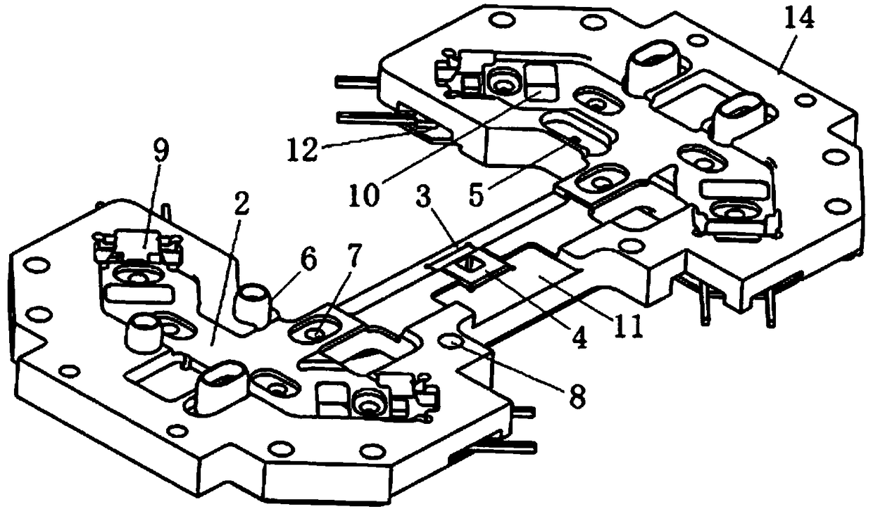
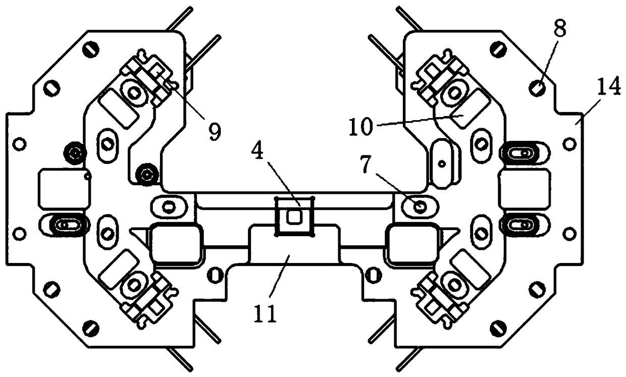
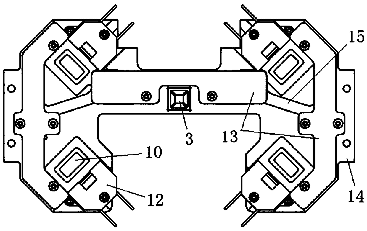
[0067] This embodiment provides a support jig 1, which is used to support the beam plate under the beam plate for fixed connection when the beam plate at the bottom of the notebook computer touch panel is detected, such as Figure 1~4 As shown, the support fixture 1 includes a workpiece accommodating groove 2, an avoidance detection hole 3, an avoidance hole fixture 4, a positioning column connection groove 5, a workpiece positioning column 6, a vacuum inlet 7, a vacuum outlet 8, and a backlight Through hole 9, avoidance positioning hole 10, fixture sliding groove 11, LED light source 12, light source line fixing plate 13, and fixed connection boss 14.

[0068] The workpiece accommodating groove 2 is located on the front of the supporting jig 1 , the workpiece accommodating groove 2 matches the shape of the detected workpiece, and the back of the workpiece can be placed flat in the workpiece accommodating groove 2 .

[0069] The position avoidance detection hole 3 is a through...

Embodiment 2

[0099] This embodiment provides a positioning carriage 16, which is used to connect and move the supporting jig 1, and cooperates with the supporting jig 1 to jointly fix the workpiece to be detected, so as to prevent the workpiece from shifting when the positioning carriage 16 moves, such as Figure 5-9 As shown, the positioning carriage 16 includes: a sliding main board 17 , a main sliding fixture 18 and a side sliding fixture 19 .

[0100] The sliding main board 17 has a groove for accommodating the supporting jig 1, and bolt holes for fixed connection with the supporting jig 1 are provided on both sides of the groove, and the supporting jig 1 can be fixed on the sliding main board after the bolt passes through the bolt hole. 17 in the groove; the bottom position on both sides of the sliding main board 17 is provided with a connection hole for connecting with the first sliding table module 30, after the sliding table block of the first sliding table module 30 is fixed on the...

Embodiment 3

[0117] This embodiment provides a detection station, which is used to set the workpiece on it, and then move the workpiece to the detection position, so that the workpiece can be detected on the detection workbench, such as Figure 10-13 As shown, the detection station includes: a positioning carriage 16 , a fixed table 28 , a hydraulic drive rod 29 , and a first slide module 30 .

[0118] The first slide module 30 that is used to connect the positioning carriage 16 is provided on the fixed table surface 28, and the positioning carriage 16 can slide on the first slide module 30, so that the objects fixed on the positioning carriage 16 The workpiece moves to the detection position; the positioning carriage 16 has two groups juxtaposed on the fixed table surface 28, and the positioning carriage 16 of the two groups has a separate driving device to drive. When testing, one group of positioning carriages 16 The workpiece detection can be carried out on it, and the other set of pos...


PUM


Abstract

The invention provides a detection apparatus positioning method, belonging to the technical field of dimension inspection of a workpiece structure. The detection apparatus positioning method comprisesthe following steps: image scanning a support tool located at a preset workpiece detection position by a scanning apparatus; obtaining the position of the support tool according to at least three positioning points on the support tool, thereby determining a precise position of the workpiece fixed to the support tool; controlling the detection apparatus to move to a preset workpiece detection initial position according to the precise position of the workpiece. The invention uses the image scanning to determine the position of the support tool. According to the detection apparatus positioning method, the adaptive adjustment can be automatically made according to the position change of the support tool, so that the detection apparatus can always accurately find the position of the support tool, thereby improving the alignment accuracy of the preset detection initial position on the workpiece, improving the detection effect on the workpiece.

Description

technical field [0001] The invention relates to the technical field of workpiece structural dimension inspection and detection, in particular to a detection device positioning method. Background technique [0002] When testing computer hardware workpiece products, it is usually necessary to place the workpiece to be tested on the supporting jig, then move the jig carrying the workpiece to the testing position through the positioning carriage, and then use the testing equipment to detect the workpiece on the jig. [0003] When it is necessary to detect multiple parallel workpieces, the detection equipment needs to move between multiple detection positions. The detection location of the detection device. [0004] However, the detection position determined by pre-commissioning is a fixed position. When the workpiece placed on the jig is displaced by a small distance, the detection equipment will not be able to accurately align the workpiece, which will affect the detection eff...

Claims


Application Information

Patent Timeline
Patent Type & Authority Applications(China)
IPC IPC(8): G01B11/06G01B11/24G01B11/08G01B11/26
CPCG01B11/06G01B11/08G01B11/24G01B11/26
Inventor 吴加富缪磊周平周明斌郭康泰
Owner SUZHOU RS TECH
Why Eureka
Try Eureka