Method for estimating separation trajectory of stage separation wind tunnel free flight test model

A flight test and model technology, applied in the direction of aerodynamic test, machine/structural component test, measuring device, etc., can solve the problems of wind tunnel blowing times test model waste, test effective times reduction, test model waste, etc., to achieve The effect of saving test cost, simple method and convenient use

Active Publication Date: 2019-01-18
CHINA ACAD OF AEROSPACE AERODYNAMICS
View PDF7 Cites 12 Cited by
  • Summary
  • Abstract
  • Description
  • Claims
  • Application Information

AI Technical Summary

Problems solved by technology

[0006] Since the test model of the wind tunnel free flight test is lossy, one model will be lost for each test, so if the separation process of the model cannot be displayed in the wind tunnel observation window area, the effective number of tests will be reduced or invalid times, which will result in a waste of wind tunnel blowing times and test models, increasing test costs
However, if the launch speed and launch position are repeatedly adjusted through the actual wind tunnel free flight test results again and again, it will also cause a large waste of wind tunnel blowing times and test models. Therefore, if certain launch parameters and launch positions can be adjusted before the test In this case, the separation process of the aircraft model and the situation of the flight trajectory passing through the observation window area after separation are estimated, and then the entire separation process of the aircraft model and the certain flight trajectory of each separation body after separation are observed in the wind tunnel. The required initial launch parameters and initial launch position of the aircraft model within the window range will be of great significance to ensure the test effect and reduce the cost of the wind tunnel free flight test

Method used


Image

  • Method for estimating separation trajectory of stage separation wind tunnel free flight test model
  • Method for estimating separation trajectory of stage separation wind tunnel free flight test model
  • Method for estimating separation trajectory of stage separation wind tunnel free flight test model

Examples


Embodiment Construction

[0035] The present invention will be further described in detail below in conjunction with the accompanying drawings, so that those skilled in the art can implement it with reference to the description.

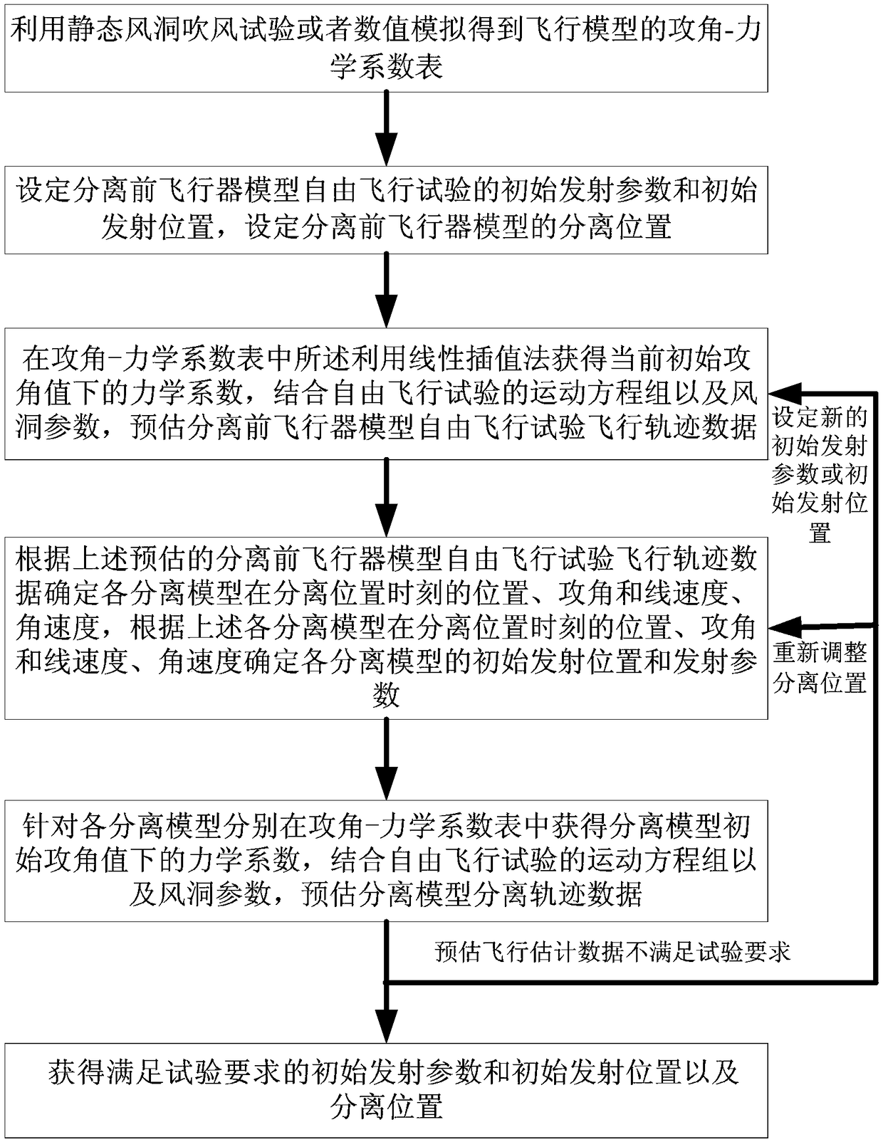
[0036] The invention discloses a method for predicting the flight trajectory of a wind tunnel free flight test model, such as figure 1 As shown, the method includes at least:

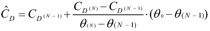
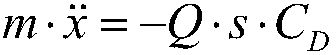
[0037] Step 1, using static wind tunnel blowing test or numerical simulation to obtain a plurality of angles of attack and mechanical coefficient data corresponding to the angle of attack of the aircraft model before separation and each separation body model after separation, and obtain the angle of attack- Table of mechanical coefficients; the mechanical coefficients include: resistance coefficient C D , lift coefficient C L and the pitching moment coefficient C M .

[0038] Preferably, the angle of attack-mechanical coefficient table is arranged in ascending order according to the angle of attack...


PUM


Abstract

The invention discloses a method for estimating a separation trajectory of a stage separation wind tunnel free flight test model. The method comprises the following steps of 1, determining an attack angle-mechanical coefficient table of an aircraft model before separation and separated body models after separation; 2, setting initial launching parameters and an initial launching position of a freeflight test of the aircraft model before separation, and setting the separation position of the aircraft model before separation; 3, estimating flight trajectory data of the free flight test of the aircraft model before separation; 4, determining initial launching positions and launching parameters of the separated models; 5, estimating separation trajectory data of the separated models; and 6, judging whether the separation trajectory data of the separated body models meet the test requirements or not, and if not, resetting the initial launching parameters/launching position values in the step 2, starting execution from the step 3 again, until the separation trajectory data of the separated body models meet the test requirements; or readjusting the separation position, and starting execution from the step 4, until the separation trajectory data of the separated body model meets the test requirements.

Description

technical field [0001] The invention belongs to the field of special wind tunnel tests, and in particular relates to a method for predicting the separation trajectory of a free flight test model in an inter-stage separation wind tunnel. Background technique [0002] Wind tunnel free flight test is an important method in the study of aircraft dynamic characteristics and multi-body separation problems. The test principle is to truly reproduce the dynamic characteristics of the aircraft under the action of unsteady aerodynamic force or the multi-body interference during the separation process under the condition of ensuring that the wind tunnel test is similar to the dynamics of the flight state. Directly record and observe the movement characteristics or separation process of the aircraft. At the same time, based on the aerodynamic parameter identification technology, according to the angular displacement and linear displacement data of the model recorded by the high-speed cam...

Claims


Application Information

Patent Timeline
Patent Type & Authority Applications(China)
IPC IPC(8): G01M9/08
CPCG01M9/08
Inventor 蒋增辉宋威薛飞王誉超鲁伟
Owner CHINA ACAD OF AEROSPACE AERODYNAMICS
Why Eureka
Try Eureka