An assembly device and an assembly method of a rotor shaft of a motor

A technology for motor rotor shafts and assembly equipment, which is applied in the direction of electromechanical devices, manufacturing motor generators, manufacturing stator/rotor bodies, etc., can solve the problems of cumbersome operation, high danger, and workers being scalded by steel sheets, so as to improve safety, Heating speed is fast and the effect of improving work efficiency

Pending Publication Date: 2019-01-18
宁波均普智能制造股份有限公司
View PDF0 Cites 3 Cited by
  • Summary
  • Abstract
  • Description
  • Claims
  • Application Information

AI Technical Summary

Problems solved by technology

[0002] The motor rotor is generally formed by a plurality of steel sheets connected in series on the rotor shaft. The steel sheet and the rotor shaft are interference fit. In order to facilitate assembly, the existing motor rotor assembly method generally uses the rotor shaft Cool in liquid nitrogen, and insert the rotor shaft into the rotor shaft installation hole of the steel sheet after being cooled and shrunk. At present, the assembly of the extremely low-temperature rotor shaft into the steel sheet is done manually, which is easy to frostbite and extremely dangerous. Big
[0003] Alternatively, put the steel sheet into heating equipment such as an oven to heat it to expand, then take out the steel sheet from the oven, and then insert the rotor shaft into the rotor shaft mounting hole of the steel sheet. When quickly assembling the rotor shaft and the steel sheet, the assembly may not be possible or the assembly effect is not good, which increases the scrap rate. On the other hand, the high temperature steel sheet may burn the workers, which is very dangerous

Method used


Image

  • An assembly device and an assembly method of a rotor shaft of a motor
  • An assembly device and an assembly method of a rotor shaft of a motor
  • An assembly device and an assembly method of a rotor shaft of a motor

Examples


Embodiment 1

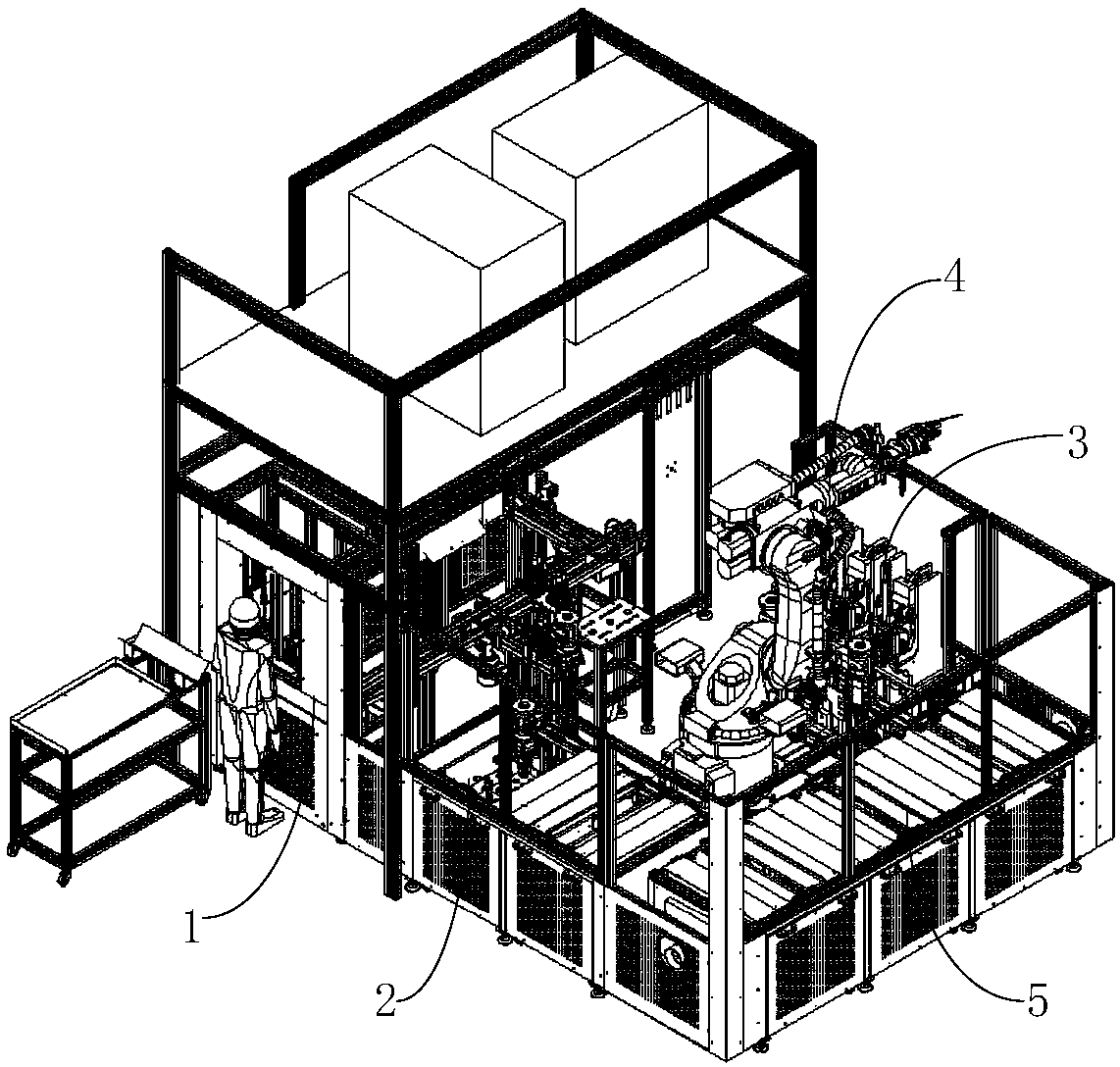
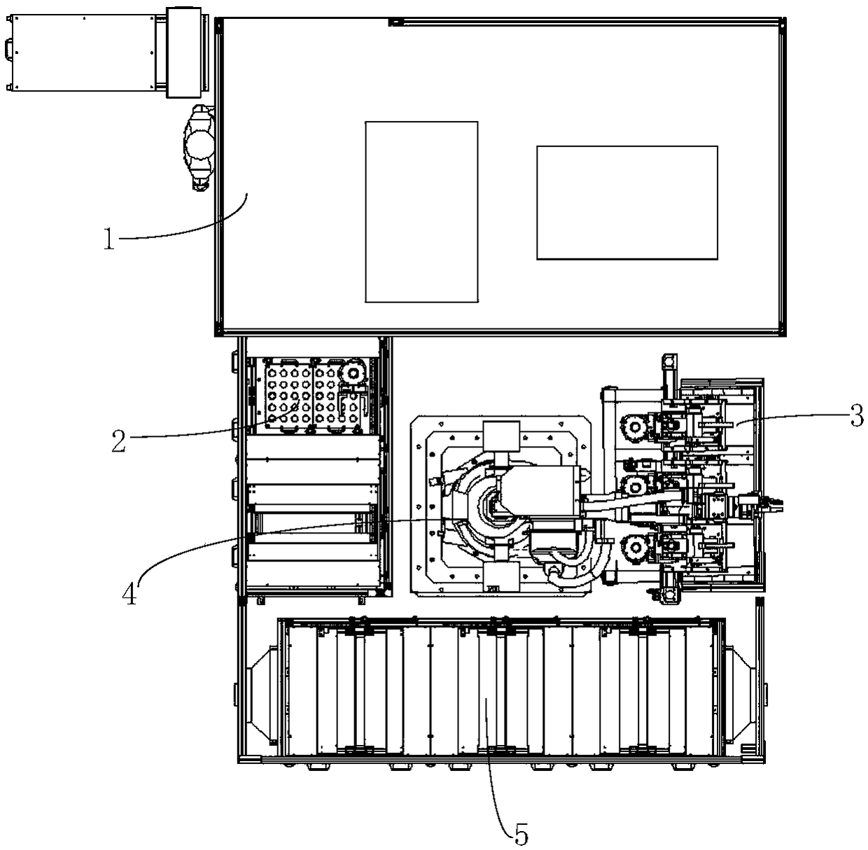
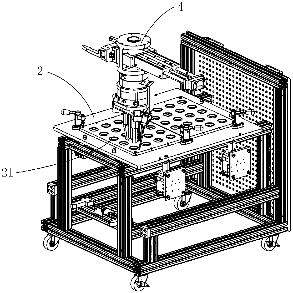
[0044] see Figure 1 to Figure 9 As shown, they are respectively the perspective view of the overall structure of the rotor shaft of the motor of the present invention, the top view of the overall structure, the structural diagram of the rotor shaft feeding station, the partial structural diagram of the manipulator, the structural diagram of the heating assembly station, and the structural diagram of the press-fitting device , A partial diagram of the heating assembly station, a structural diagram of the heating device and a structural diagram of the heating rod.

[0045] combine Figure 1 to Figure 9 As shown, an assembly equipment for a motor rotor shaft includes a manipulator 4 and a silicon steel sheet feeding station 1 arranged around the manipulator 4, a rotor shaft feeding station 2, a heating assembly station 3, and a rotor cooling station 5. The material station 1 includes a manual assembly station, a pressing device for pressing the motor rotor semi-finished product...

Embodiment 2

[0054] As for the assembly equipment of the motor rotor shaft described in Embodiment 1, the difference of this embodiment is that the two ends of the spiral conductive member 331 are provided with conductive connecting rods, and the conductive connecting rods are electrically connected so as to facilitate the connection of the spiral conductive member. 331 power supply.

Embodiment 3

[0056] As the assembly equipment of the motor rotor shaft described in the second embodiment, the difference of this embodiment is that, as Figure 10 As shown, the number of metal rods 332 is two, respectively the first metal rod 3321 and the second metal rod 3322; one end of the first metal rod 3321 is connected to one end of the spiral conductive member 331, and the other One end is electrically connected; one end of the second metal rod 3322 is connected to the other end of the spiral conductive member 331 , and the other end of the second metal rod 3322 is electrically connected.

[0057] The assembling equipment of the motor rotor shaft in the present invention directly connects the metal rods 332 electrically, saves two conductive connecting rods, has a simple and compact structure, and has a beautiful appearance.


PUM


Abstract

The invention provides an assembly apparatus and an assembly method of a rotor shaft of a motor. the assembly apparatus for motor rotor shafts includes manipulators, silicon steel sheet loading stations, a heating assembly station, and rotor shaft loading stations; a load station of silicon steel sheet comprises a manual assembly station, a pressing device and a jig cooling station. that heatingassembly station comprises a heating device, a heating rod is arranged on the heating device, the heat rod comprises at least one helical conductive member, and at least one metal rod is arranged in each helical conductive member. the electric motor rotor shaft assembly device of the invention combines the heating rod and the silicon steel sheet to form eddy current, and realizes the self-heatingof the silicon steel sheet by utilizing the eddy current induction principle. The heating mode not only has extremely fast heating speed, but also the heating rod itself does not heat, thus improvingthe safety of the operation of the device.

Description

technical field [0001] The invention relates to the technical field of motor manufacturing, in particular to an assembly device and an assembly method for a motor rotor shaft. Background technique [0002] The motor rotor is generally formed by a plurality of steel sheets connected in series on the rotor shaft. The steel sheet and the rotor shaft are interference fit. In order to facilitate assembly, the existing motor rotor assembly method generally uses the rotor shaft Cool in liquid nitrogen, and insert the rotor shaft into the rotor shaft installation hole of the steel sheet after being cooled and shrunk. At present, the assembly of the extremely low-temperature rotor shaft into the steel sheet is done manually, which is easy to frostbite and extremely dangerous. Big. [0003] Alternatively, put the steel sheet into heating equipment such as an oven to heat it to expand, then take out the steel sheet from the oven, and then insert the rotor shaft into the rotor shaft mo...

Claims


Application Information

Patent Timeline
IPC IPC(8): H02K15/02H02K15/12
CPCH02K15/02H02K15/12
Inventor 赖志威
Owner 宁波均普智能制造股份有限公司
Why Eureka
Try Eureka