A simple photoreflective synergistic device for a fixed plate photovoltaic module array power generation system

A technology for photovoltaic modules and power generation systems, applied in photovoltaic power generation, support structures of photovoltaic modules, photovoltaic modules, etc., can solve problems such as practical application of utility models, inability to be directly practical, and complex basic structures.

Pending Publication Date: 2019-01-18
NANCHANG UNIV
View PDF2 Cites 1 Cited by
  • Summary
  • Abstract
  • Description
  • Claims
  • Application Information

AI Technical Summary

Problems solved by technology

However, the proposed basic structure is also too complicated, and multiple brackets need to be configured for each reflector, which is costly, and there is no explanation for how to connect and fix the brackets, reflectors and components, so it cannot be directly used; and the utility model is also It does not involve how to deal with the first row of modules without adjacent rows. In the actual application of photovoltaic power generation system, the detuning loss will be caused by the inconsistent lighting conditions of the first row of modules and other rows of modules in the string, and there will be no synergistic effect; In addition, this utility model does not take into account that the system needs to restore the inspection channel between the rows of modules when necessary, so that the system cannot be repaired, or it cannot make full use of the solar energy efficiency of the row intervals between modules.
Due to the problems referred to above, the practical application of this utility model has not been seen so far

Method used


Image

  • A simple photoreflective synergistic device for a fixed plate photovoltaic module array power generation system
  • A simple photoreflective synergistic device for a fixed plate photovoltaic module array power generation system
  • A simple photoreflective synergistic device for a fixed plate photovoltaic module array power generation system

Examples


Embodiment 1

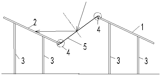
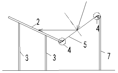
[0023] Select a fixed flat-panel photovoltaic module array power generation system installed on a flat roof, which is composed of 2 rows and 3 columns, a total of 6 polysilicon photovoltaic modules connected in series. The size of the photovoltaic module is 1.64m×0.99m, it is inclined towards the south, and the angle between the inclination and the ground plane is 25 degrees, and the horizontal distance between the rows of photovoltaic modules is 1.06m. The white aluminum-plastic panel is used as the reflector. The width of the reflector is the same as that of the photovoltaic module, and the length is 1.2m, which satisfies figure 1 The overlapping conditions between the two rows of photovoltaic modules shown and the front and back. Each pair of photovoltaic modules in the front and rear rows is equipped with a reflector; the first row of photovoltaic modules in the front is equipped with a reflector bracket, such as image 3 As shown, each photovoltaic module is equipped wi...

Embodiment 2

[0026] Select a fixed flat-panel photovoltaic module array power generation system installed on a flat roof, which is composed of 2 rows and 3 columns, a total of 6 polysilicon photovoltaic modules connected in series. The size of the photovoltaic module is 1.64m×0.99m, it is inclined towards the south, and the angle between the inclination and the ground plane is 25 degrees, and the horizontal distance between the rows of photovoltaic modules is 1.06m. The white aluminum-plastic panel is used as the reflector. The width of the reflector is the same as that of the photovoltaic module, and the length is 1.2m, which satisfies figure 1 The overlapping conditions between the two rows of photovoltaic modules shown and the front and back. Each pair of photovoltaic modules in the front and rear rows is equipped with a reflector; the first row of photovoltaic modules in the front is equipped with a reflector bracket, such as image 3 As shown, each photovoltaic module is equipped wi...

Embodiment 3

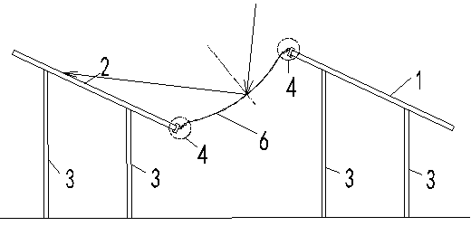
[0029] Select a fixed flat-panel photovoltaic module array power generation system installed on a flat roof, which is composed of 2 rows and 3 columns, a total of 6 polysilicon photovoltaic modules connected in series. The size of the photovoltaic module is 1.64m×0.99m, it is inclined towards the south, and the angle between the inclination and the ground plane is 25 degrees, and the horizontal distance between the rows of photovoltaic modules is 1.06m. White polystyrene foam boards are used as reflectors. The width of the reflector is the same as that of the photovoltaic module, and the length is 1.2m, which satisfies figure 1 The overlapping conditions between the two rows of photovoltaic modules shown and the front and back. Each pair of photovoltaic modules in the front and rear rows is equipped with a reflector; the first row of photovoltaic modules in the front is equipped with a reflector bracket, such as image 3 As shown, each photovoltaic module is equipped with a ...


PUM


Abstract

A simple reflective synergistic device for a fixed flat panel photovoltaic module array power generation system comprises a front photovoltaic module, a rear photovoltaic module and a module bracket,wherein a light reflecting plate is installed between the front photovoltaic module and the rear photovoltaic module in a neutral position, one end of the light reflecting plate is connected with thetop edge of the front photovoltaic module through a light reflecting plate connecting piece, and the other end of the light reflecting plate is connected with the bottom edge of the rear photovoltaicmodule through the light reflecting plate connecting piece. The invention can be used for designing a new photovoltaic power generation system, and can also be used for installing the built photovoltaic power generation system. It can increase the output of power generation when the system works normally, advance the starting time when the system reaches the power generation threshold, postpone the closing time when the system falls below the power generation threshold, and effectively improve the power generation efficiency of the system. The design and implementation are simple, and the reflector material used can be any plate material with light reflection and scattering ability, the cost is low, and the power generation cost can be effectively reduced.

Description

technical field [0001] The invention belongs to the technical field of photovoltaic power generation systems, and relates to a method for increasing efficiency of a fixed flat-plate photovoltaic module array power generation system. Background technique [0002] So far, the fixed flat-panel photovoltaic module array power generation system is still the mainstream of photovoltaic power generation technology. Reducing the cost of power generation is an ongoing goal of photovoltaic technology development. Reducing the cost of solar cells and improving the energy conversion efficiency of solar cells has been an important means for the industry to reduce the cost of photovoltaic power generation for many years, but so far the development space in this area has been very limited. [0003] Southeast University once disclosed an invention (CN104167982A) that increases the output of photovoltaic power generation by placing reflective panels between module rows. However, the propose...

Claims


Application Information

Patent Timeline
Patent Type & Authority Applications(China)
IPC IPC(8): H02S40/22H02S20/24
CPCH02S20/24H02S40/22Y02B10/10Y02E10/52
Inventor 胡琳周浪曾庆国黄海宾
Owner NANCHANG UNIV
Why Eureka
Try Eureka