A light and speed regulating circuit

A circuit and speed regulation technology, which is applied in the direction of electric lamp circuit layout, light source, electric light source, etc., can solve the problems of dead travel, inconvenience, etc.

Pending Publication Date: 2019-01-18
XIAMEN TENIA LIGHTING & ELECTRICAL
View PDF0 Cites 5 Cited by
  • Summary
  • Abstract
  • Description
  • Claims
  • Application Information

AI Technical Summary

Problems solved by technology

[0010] The main purpose of the present invention is to propose a dimming and speed regulating circuit, so that the work of the lamp is at or close to the minimum brightness state that the lamp itself can maintain itself after the dimming switch is closed, or the fan is in the state after the governor switch is closed. Maintain the minimum working current state to solve the problem of dead travel (invalid travel) and inconvenient use when starting up (after the dimmer switch and speed control switch are closed)

Method used


Image

  • A light and speed regulating circuit
  • A light and speed regulating circuit
  • A light and speed regulating circuit

Examples


Embodiment 1

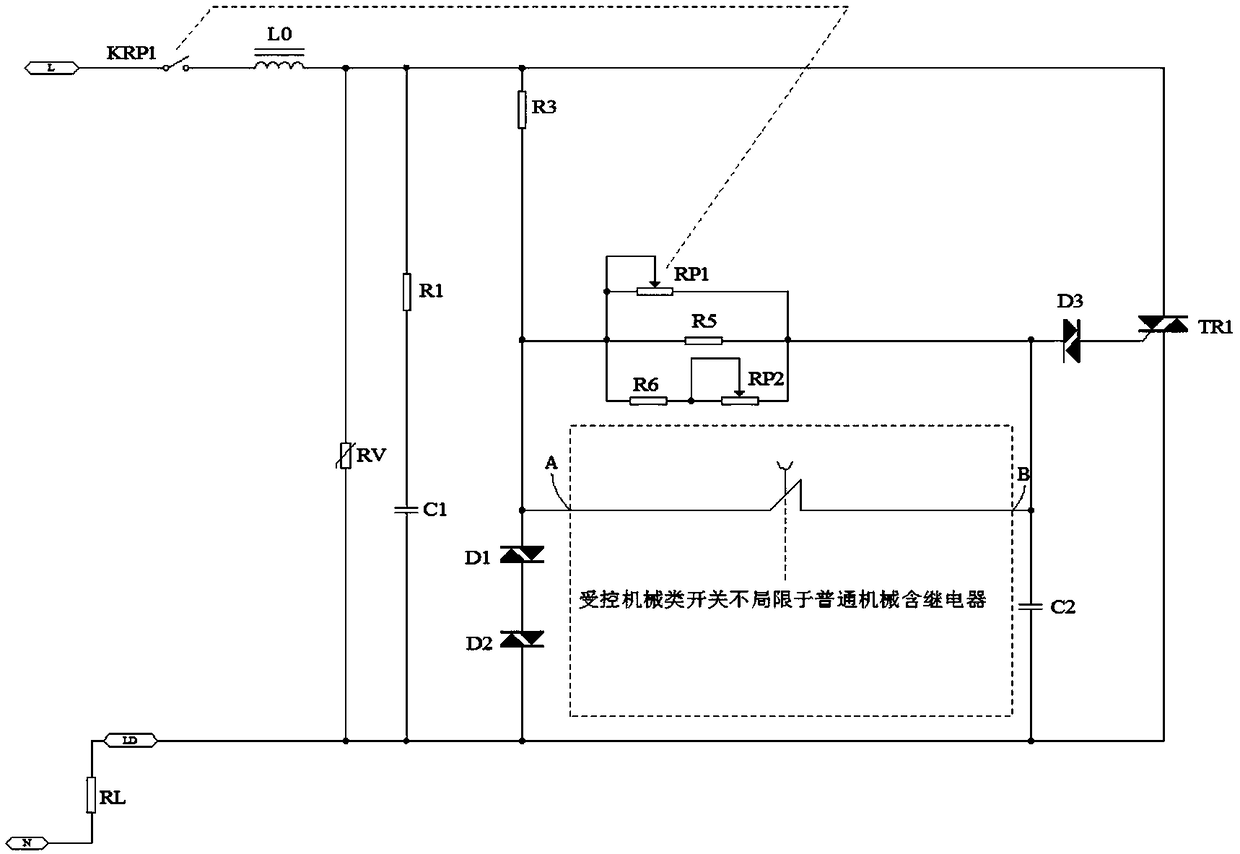
[0045] see Figure 5 As shown, in this embodiment, the ABC circuit network in the dotted line frame is composed of a relay and a corresponding controlled electronic timing off switch to realize the compensation circuit of the compensation current, specifically including: the fourth diode D4, the fifth diode D5 , the seventh resistor R7, the eighth resistor R8, the normally open relay, the sixth diode D6, the seventh diode D7, the bridge rectifier BD1, the ninth resistor R9, the voltage stabilizing module IC1, the fourth capacitor C4, the Ten resistors R10, eleventh resistors R11, and the second switch tube Q2; the cathode of the fourth diode D4, the anode of the fifth diode D5, and an AC input terminal of the rectifier bridge stack BD1 are respectively connected to the The input ends of the adjustable resistance network are connected; the anode of the fourth diode D4, the seventh resistor R7, the first contact K1 of the relay, and the cathode of the sixth diode D6 are connecte...

Embodiment 2

[0051] see Figure 6 As shown, in this embodiment, the ABC circuit network in the dotted line frame forms a compensation circuit for controlling electronic timed off switches to realize compensation current, specifically including: the fourth diode D4, the fifth diode D5, and the seventh resistor R7 , the eighth resistor R8, the sixth diode D6, the seventh diode D7, the rectifier bridge stack BD1, the third capacitor C3, the ninth resistor R9, the tenth resistor R10, the eleventh resistor R11, the twelfth resistor R12, Zener tube ZD1, first switch tube Q1, second switch tube Q2 and third switch tube Q3; the cathode of the fourth diode D4, the anode of the fifth diode D5, the rectifier bridge stack BD1 An AC input terminal is respectively connected to the input terminal of the adjustable resistor network; the anode of the fourth diode D4, the third switching tube Q3, the seventh resistor R7, and the cathode of the sixth diode D6 are connected in series in sequence connected; t...

Embodiment 3

[0057] see Figure 7 , in this embodiment, the ABC circuit network in the dotted line frame forms a compensation circuit for controlling electronic timing off switches to realize the compensation current, specifically including: the seventh diode D7, the eighth diode D8, the eighth resistor R8, the first Nine resistors R9, tenth resistor R10, twelfth resistor R12, third capacitor C3, voltage regulator tube ZD1, first switch tube Q1 and second switch tube Q2; one end of the ninth resistor R9 is connected to the adjustable The input terminals of the resistor network are connected; the other end of the ninth resistor R9 is connected to one end of the eighth resistor R8, one end of the tenth resistor R10, and one end of the eleventh resistor R11 respectively; The other end of the eighth resistor R8 is connected to the input end of the first switching tube Q1; the output end of the first switching tube Q1 is connected to the anode of the seventh diode D7; the seventh The cathode o...


PUM


Abstract

The invention discloses a light and speed regulating circuit, which comprises a main trigger circuit connected in series between a fire line terminal and a neutral line terminal and used for regulating load brightness or load speed through an adjustable resistor network and a switch actuating element, and a compensation circuit connected in parallel with the adjustable resistor network; the compensation circuit provids current compensation to the adjustable resistor network for a period of time after the power switch is closed to satisfy the start-up current of the load and to continuously turn on the switch actuating element for the period of time; The power switch is connected with the fire line end; The switching actuator comprises a silicon-controlled rectifier, a MOS transistor, an IGBT and / or a thyristor. The invention makes the operation of the lamp in or close to the minimum self-sustaining brightness state of the lamp itself after the dimming switch is closed, or the fan be inthe minimum sustaining working current state after the speed regulator switch is closed, so as to solve the problems of dead stroke (invalid stroke) and inconvenience in use when starting the machine.

Description

technical field [0001] The invention relates to the technical field of dimming and speed regulation, in particular to a dimming and speed regulating circuit. Background technique [0002] Conventional thyristor dimming, governor circuit schematic diagram see figure 1 As shown, when the switch KRP1 is closed, the power supply charges the trigger capacitor C2 through KRP1, Lo, R3, and the adjustable resistor network R' (composed of RP1, R5, R6, and RP2). When the voltage of the trigger capacitor C2 is charged to a value higher than When the breakdown voltage UBo of the trigger diode D3 is reached, the trigger diode D3 is turned on. After D3 is turned on, a certain current flows from the control pole G of the bidirectional thyristor TR1 to the first anode. Since the turn-on voltage of the trigger diode D3 is When the voltage drops below a certain value of the breakdown voltage, the trigger capacitor C2 has a voltage difference. At this time, the energy originally stored in the...

Claims


Application Information

Patent Timeline
Patent Type & Authority Applications(China)
IPC IPC(8): H05B37/02
CPCH05B47/10Y02B20/40
Inventor 张文龙陈元木
Owner XIAMEN TENIA LIGHTING & ELECTRICAL
Why Eureka
Try Eureka