
Methods and apparatus for robust and efficient stepper motor bemf measurement

A stepper motor, back EMF technology, applied in electronic commutation motor control, motor generator control, AC motor control and other directions, can solve the problems of inability to measure BEMF voltage, short time for BEMF voltage measurement, and limitations

Active Publication Date: 2019-01-18
TEXAS INSTR INC
View PDF5 Cites 1 Cited by
  • Summary
  • Abstract
  • Description
  • Claims
  • Application Information

AI Technical Summary

Problems solved by technology

However, these methods of measuring BEMF in stepper motors using
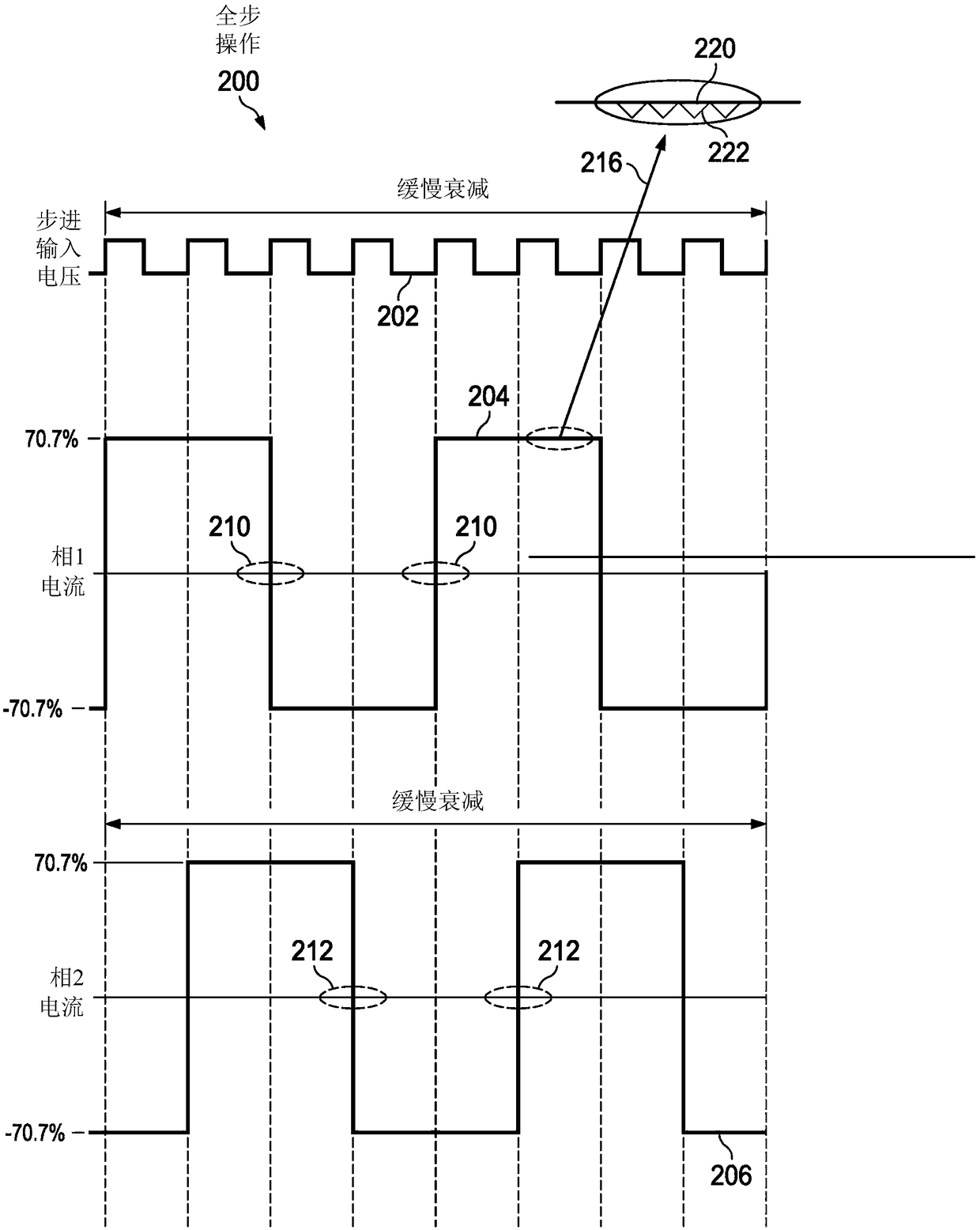
In full-step mode of a stepper motor, there is no time when the current in the motor windings is zero, so BEMF voltage measurements are not possible
In other modes of operation, the time available for BEMF voltage measurements after the initial magnetic field decay time is rather short

Method used


Image

  • Methods and apparatus for robust and efficient stepper motor bemf measurement
  • Methods and apparatus for robust and efficient stepper motor bemf measurement
  • Methods and apparatus for robust and efficient stepper motor bemf measurement

Examples


Embodiment Construction

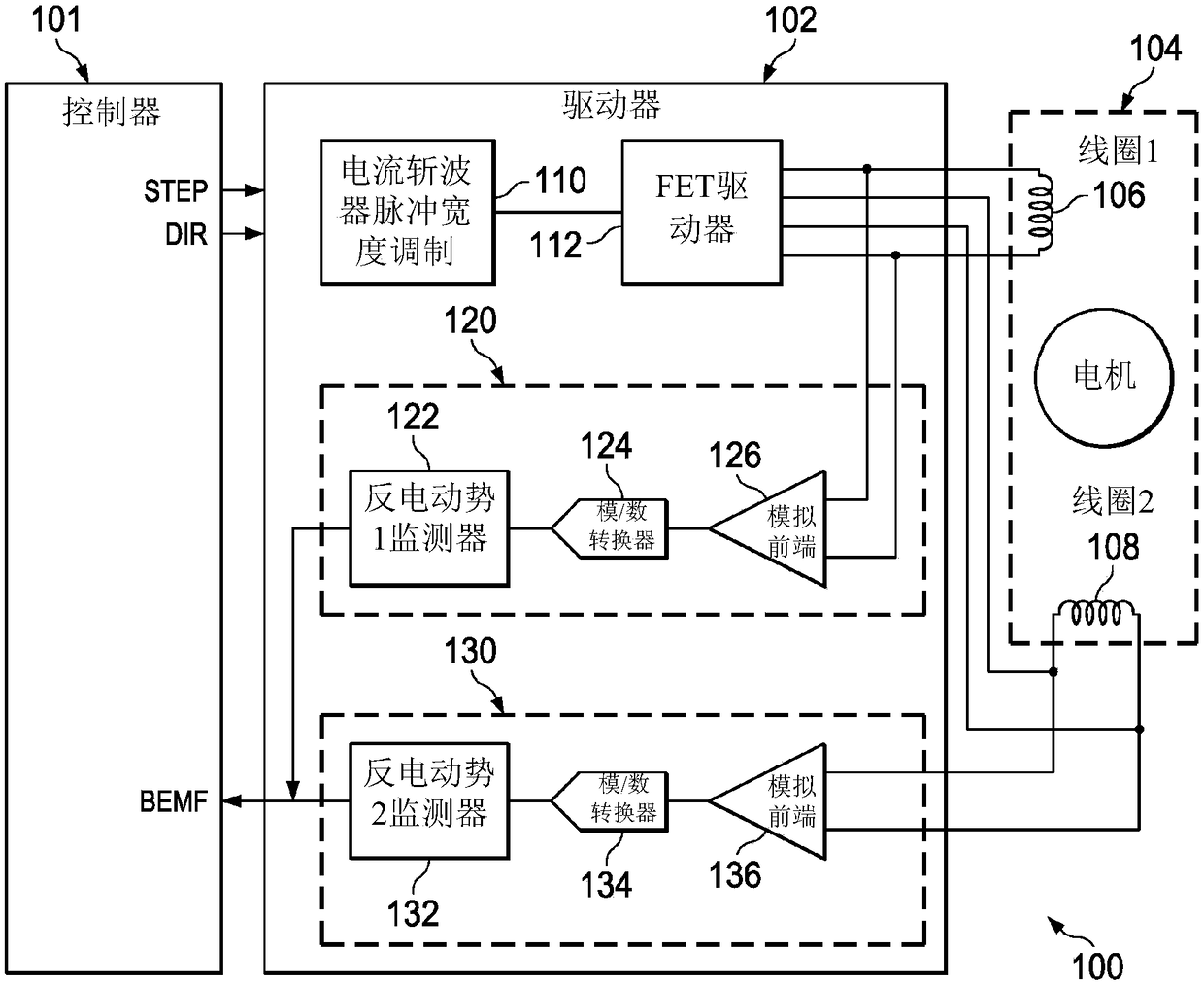
[0015] Corresponding numerals and symbols in the different figures generally refer to corresponding parts unless otherwise indicated. The figures are not necessarily drawn to scale. The term "coupled" may include connections made using intervening elements, and additional elements and various connections may exist between any elements that are "coupled".

[0016] Stepper motors provide precise mechanical movement in response to pulsed signals. Unlike DC brush motors, which operate at a speed determined by an electric potential, stepper motors rotate from one position to another with precise incremental rotations with each step. The controller provides the pulse signals needed to advance the stepper motor. A stepper motor may have a toothed iron gear that aligns with magnets around the gear. The gear changes position in response to current applied to the coil. A pulse width modulation (PWM) circuit applies pulses to the coil.

[0017] figure 1 is a block diagram of a syst...


PUM


Abstract

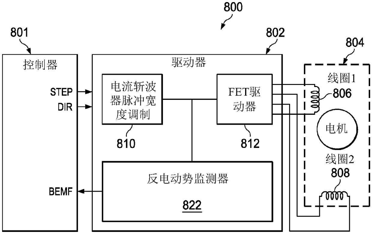
In a described example, an apparatus (800) includes: a FET driver circuit (812) configured to supply current to a coil in a stepper motor, the FET driver circuit (812) configured to regulate the current to the coil using a fixed delta current; a current chopper PWM circuit (810) coupled to the FET driver circuit (812) configured to supply pulses corresponding to a step control signal and a direction control signal; a back electromotive force (BEMF) monitor (822) coupled to the current chopper PWM circuit (810) configured to measure an off time pulse and to output a BEMF monitor signal; and a controller (801) coupled to the current chopper PWM circuit (810) to supply the step and direction control signals and coupled to receive the BEMF monitor signal.

Description

[0001] The present invention relates generally to stepper motors, and more particularly, to stepper motors with back electromotive force (BEMF) measurement. Background technique [0002] Stepper motors are externally commutated motors commonly used for positional tasks. Use an open-loop approach to control and operate a stepper motor. In this open-loop approach, the controller sends commutation signals to the motor. Open-loop control assumes that the motor responds to controller signals. Next, position is determined from the expected motor response. For lightly loaded motors and at low speeds, the open loop approach works well. However, in an open-loop stepper motor control system, the rotor may not commutate to the desired position for several reasons, including: random electrical noise; high loads; pulsed loads; and / or open circuit. These possible failures make open-loop control systems unpopular in many position-critical applications. [0003] A closed-loop approach i...

Claims


Application Information

Patent Timeline
IPC IPC(8): H02P8/04H02P8/08H02P6/18H02P27/08
CPCH02P6/182H02P8/14
Inventor S·索R·拉亚阿努吉·贾因M·海因
Owner TEXAS INSTR INC
Learn More