Pushing construction method for a large-span composite arch bridge with adjustable construction state

A jacking construction and large-span technology, applied to arch bridges, bridges, bridge forms, etc., can solve problems such as inadequacies, inability to effectively use the force of arch beams, and high construction costs

Pending Publication Date: 2019-01-22
SHANGHAI MUNICIPAL ENG DESIGN INST GRP
View PDF1 Cites 8 Cited by
  • Summary
  • Abstract
  • Description
  • Claims
  • Application Information

AI Technical Summary

Problems solved by technology

"Integral jacking method with arches for large tonnage multi-span composite arch bridge" (patent application number: CN101793010) proposes a method for integral jacking with arches, but in this method the arch beams are only temporarily connected by struts, and then installed after the jacking is completed The boom cannot be used effectively to adjust the force of the arch beam during the jacking process, and it prolongs the existence time of the temporary pier in the water, which affects the flood discharge and navigation under the bridge; "(Patent Application No.: 2011101028797) proposed the overall jacking method without guide girders for network tie-bar arch bridges, but this scheme did not consider the adjustability of the boom force during the entire construction process, and the overall jacking method without guide beams is For long-span bridges, the construction cost is high; in addition, during the construction process, the structure is a time-varying structure, the resistance of the structure is a random variable, and the load is constantly changing with the construction progress. It is difficult to fully guarantee the safety of the structure with deterministic theory to guide the construction. sex
Therefore, for long-span arch bridges, the current jacking construction method has deficiencies.

Method used


Image

  • Pushing construction method for a large-span composite arch bridge with adjustable construction state
  • Pushing construction method for a large-span composite arch bridge with adjustable construction state
  • Pushing construction method for a large-span composite arch bridge with adjustable construction state

Examples


Embodiment Construction

[0037] A kind of construction state adjustable long-span composite system arch bridge jacking construction method proposed by the present invention will be described in further detail below in conjunction with the accompanying drawings and specific examples. Advantages and features of the present invention will be apparent from the following description and claims. It should be noted that all the drawings are in very simplified form and use imprecise scales, and are only used to facilitate and clearly assist the purpose of illustrating examples of the present invention.

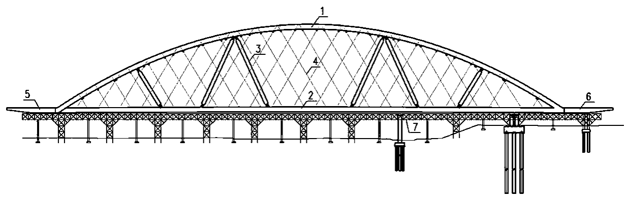
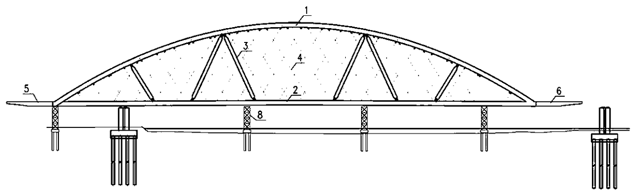
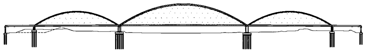
[0038] combine Figure 1 to Figure 4 Explain the jacking construction method of the large-span composite arch bridge with adjustable construction status in this example. The main process is as follows: the jacking platform 7 is erected on land, the main girder 2 is first assembled, and then the arch rib 1 is assembled horizontally on the top of the main girder and passed vertically. Put the arch rib in place...


PUM


Abstract

The invention relates to a pushing construction method for a large-span composite arch bridge with adjustable construction state, which is characterized in that a steel arch, a steel beam, a hanger and a connecting steel arch, a temporary strut of a steel beam are assembled into a beam-arch composite system on the shore in advance, and the suspension rods are pretensioned. In the process of pushing the composite arch bridge with suspension rods and temporary struts as a whole, the construction state is adjusted by optimizing the tension of suspension rods based on the structural function of component stress limits. The construction method adjusts the stress state of the composite arch bridge in real time by adjusting the tension of the suspension bar, to some extent, it ensures the cooperation of arch and beam, improves the mechanical performance of the structure, reduces the number of temporary piers and arch beam temporary struts in water, reduces the complexity of the structure construction, and has high popularization value in applicability, economy, construction quality, construction period and other aspects, which is of pioneering significance for similar projects in the future.

Description

technical field [0001] The invention relates to the technical field of bridge engineering, in particular to a jacking construction method for an arch bridge with an adjustable construction state and a large-span composite system. Background technique [0002] Composite system arch bridge occupies a place in the construction of long-span bridges because of its beautiful appearance, reasonable mechanical performance and good economy. Commonly used construction methods for composite arch bridges include support construction, swivel construction, cable hoisting construction, and jacking construction. [0003] Bracket construction method For the steel structure composite system arch bridge, the steel girder part can be installed first, and then the steel arch can be assembled on the steel girder, that is, the construction method of the beam first and then the arch. Regardless of the method used to construct the steel beam, the construction of the steel arch requires the erection...

Claims


Application Information

Patent Timeline
Patent Type & Authority Applications(China)
IPC IPC(8): E01D21/06E01D4/00
CPCE01D21/06E01D4/00
Inventor 邵长宇吴霄陈亮周伟翔张洪金
Owner SHANGHAI MUNICIPAL ENG DESIGN INST GRP
Why Eureka
Try Eureka