
Forced-cooling drain flash tank and utilization method thereof

A technology of hydrophobic expansion and forced cooling, which is applied in the direction of boiler cleaning equipment, etc., can solve the problems of reducing the efficiency of heat energy recovery and utilization, and achieve the effects of reducing emissions, reducing visual pollution, and reducing emission pollution

Pending Publication Date: 2019-01-22
陕西中河电力工程有限公司
View PDF7 Cites 0 Cited by
  • Summary
  • Abstract
  • Description
  • Claims
  • Application Information

AI Technical Summary

Problems solved by technology

[0003] The recycling and depressurization of steam are inseparable from the use of the drain expander. The existing drain expander is to expand and reduce the pressure of the drain in the pressure drain pipeline to separate the steam and drain, and the drain is introduced into the drain tank. Regularly sent to the water supply system, and the excess steam will be discharged into the atmosphere after depressurization. Because the steam contains rich heat energy, when it is discharged into the atmosphere, it will form a large amount of water mist when it encounters cold air, forming a visual appearance like white smoke. Pollution, but also reduces the recovery efficiency of heat energy

Method used


Image

  • Forced-cooling drain flash tank and utilization method thereof

Examples


Embodiment Construction

[0025] The present invention will be further described below with reference to the accompanying drawings and embodiments, and the mode of the present invention includes but not limited to the following embodiments.

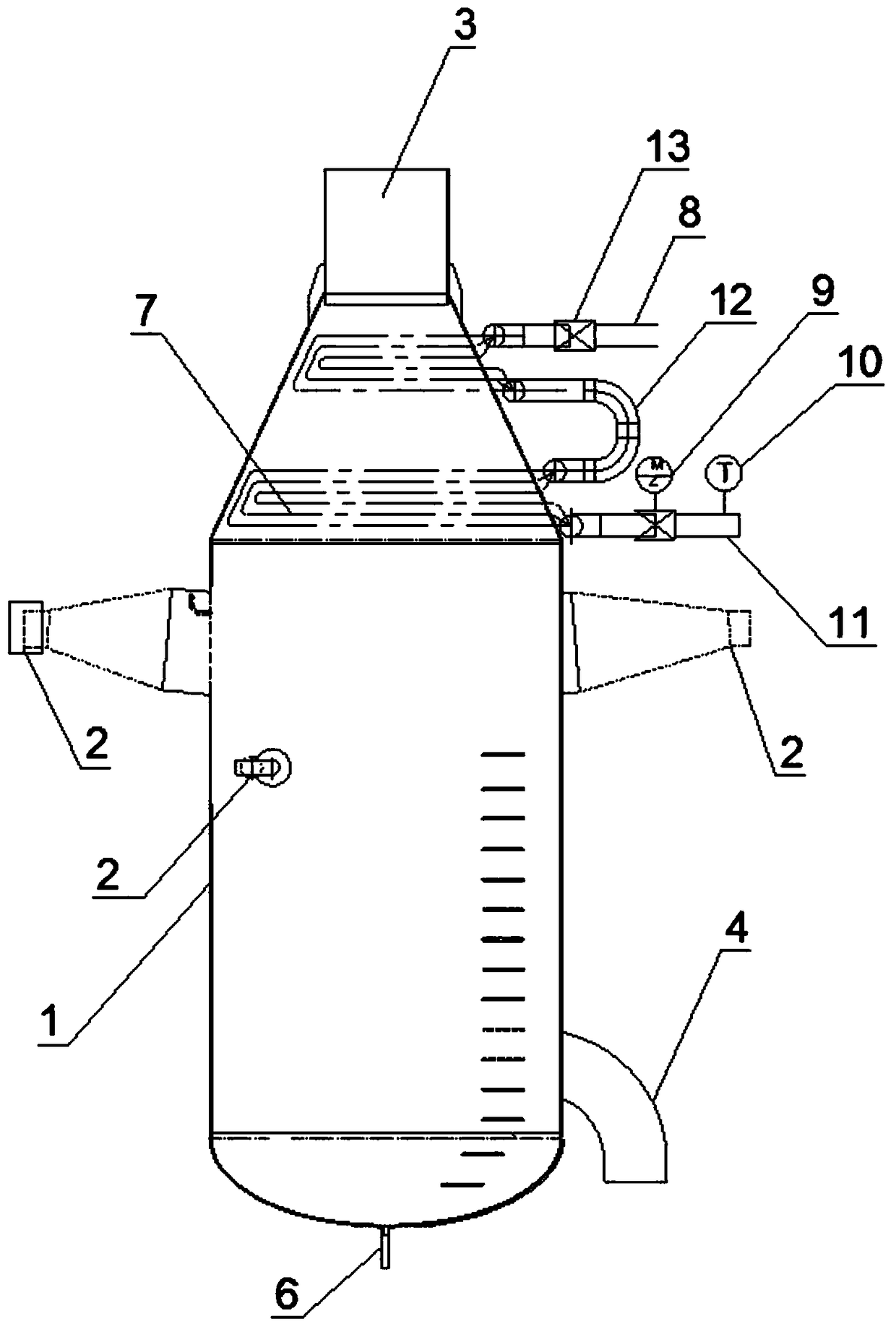
[0026] Such as figure 1 As shown, the forced cooling hydrophobic expander includes an expander body 1 with a conical upper part and a cylindrical lower part. The top of the expander body 1 is provided with a steam outlet 3, the upper part is provided with a hydrophobic inlet 2, and the lower part is provided with a The drain outlet 4 is provided with a sewage outlet 6 at the bottom. In order to meet the requirements of different sizes of drains, the drain inlet 2 includes a plurality of drains of different sizes. As in this embodiment, 3 drains of different sizes are configured, and can Choose the appropriate size of the drain port according to the size of the drain flow.

[0027] The top of the expander body 1 is provided with a cooling heat exchange tube bundle...


PUM


Abstract

The invention discloses a forced-cooling drain flash tank, which comprises a flash tank body with a conical upper portion and a cylindrical lower portion. The top of the flash tank body is provided with a steam outlet, the upper portion is provided with a drain inlet, the lower portion is provided with a drain outlet, and the bottom is provided with a sewage outlet. A cooling heat exchange tube bundle is arranged at the inner top of the flash tank body, an inlet and an outlet of the cooling heat exchange tube bundle are provided with a condensate inlet and a condensate outlet respectively, a check valve is arranged at the condensate inlet, and an electric regulating valve and a temperature sensor are arranged at the condensate outlet. The invention further discloses a utilization method ofthe forced-cooling drain flash tank. By arrangement of the cooling heat exchange tube bundle at the top steam outlet of the drain flash tank, steam recycling is further promoted, steam emission is reduced, and accordingly visual pollution caused by steam emission is reduced.

Description

technical field [0001] The invention relates to the field of energy saving and emission reduction in thermal power plants, in particular to a forced-cooling hydrophobic expander and a method for using the same. Background technique [0002] The thermal power plant burns the fuel in the boiler, releases the heat, and transfers it to the water in the boiler to generate high-temperature and high-pressure steam. The steam passes through the steam turbine and converts heat energy into rotational power to drive the generator to output electric energy. In the process of power generation, a large amount of steam needs to be generated to drive the generator. After the steam drives the generator, it will be discharged, and the discharged steam contains a large amount of heat energy. In order to further utilize the energy, the steam needs to be The energy is recovered and utilized, while reducing the pressure of the steam to ensure safe discharge. [0003] The recycling and depressuri...

Claims


Application Information

Patent Timeline
Patent Type & Authority Applications(China)
IPC IPC(8): F22B37/50
CPCF22B37/50
Inventor 赵兴春高文彬
Owner 陕西中河电力工程有限公司
Learn More