
Switch regulator

A switching regulator and switching technology, applied in the field of DC buck and voltage transformation, can solve the problems of small adjustment range, large volume, and high power consumption.

Inactive Publication Date: 2019-01-22
曹兵
View PDF0 Cites 0 Cited by
  • Summary
  • Abstract
  • Description
  • Claims
  • Application Information

AI Technical Summary

Problems solved by technology

The disadvantage of this voltage regulation mode is that it is bulky, consumes a lot of power, and the adjustment range is small.
Voltage regulation mode Single DC If you want to regulate voltage, you must first use the vibration circuit to convert it into AC

Method used


Image

  • Switch regulator
  • Switch regulator

Examples


Embodiment Construction

[0011] The present invention will be further described below in conjunction with the accompanying drawings.

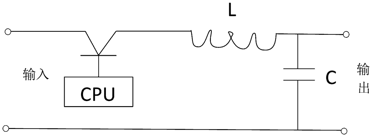
[0012] Switching voltage reducer described in the present invention such as Figure 1 As shown, the input voltage is set to 100V, and the pulse width of k is set to 2ms according to the inductance L. The duty cycle is 50%, then the output voltage is 50v, if the output current is L, then the input current should be 2L.

[0013] If the output is AC, two sets are available Figure 1 The circuit is responsible for working in both positive and negative directions. AC step-down can be performed.

[0014] right figure 1 A certain combination of circuits can also realize DC-AC step-down and AC-DC step-down.

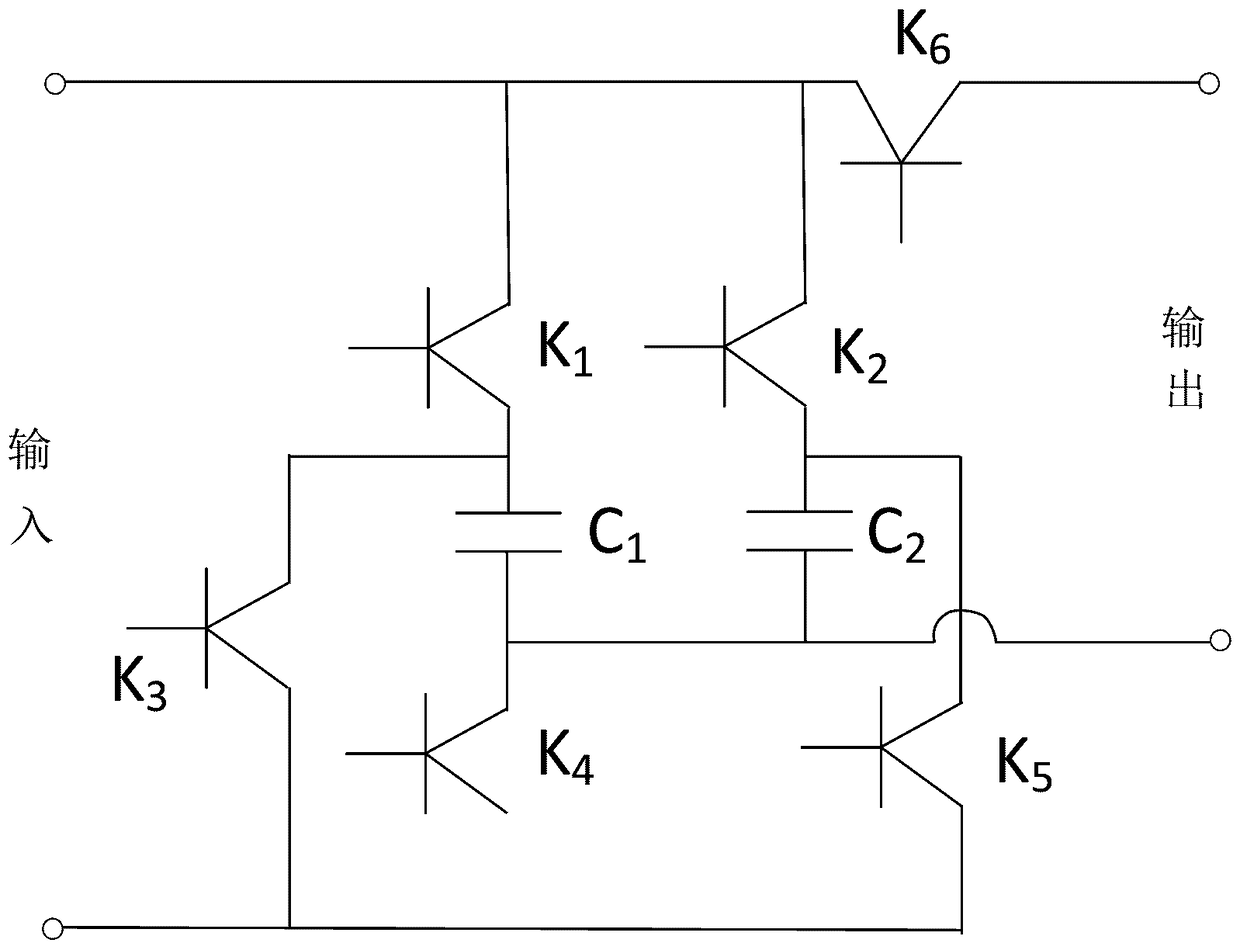
[0015] The switching booster of the present invention is as Figure II As shown, the output voltage is set to 10V, the CPU connects k1, k4 charges C1 to 10V, disconnects k1, k4 connects k3, and k2 connects the power supply and C1 in series to charge C2 to 20v. Turn...


PUM


Abstract

The invention provides a switch regulator which uses a time ratio (duty ratio) of on time and off time of a switching tube under the control of a computer by using an moss (or crystal) switching tube,a controllable semiconductor or other high-speed switching elements to control a ratio of an input voltage to an output voltage, so as to achieve the purpose of reducing the voltage. The purpose of boosting the voltage is achieved by using the series connection of a capacitor and a power supply.

Description

technical field [0001] The invention relates to the fields of voltage transformation, voltage regulation, rectification and inverter. In particular, it involves the fields of DC step-down and DC step-up. Background technique [0002] The current voltage regulating equipment uses the principle of electromagnetic conversion to achieve the purpose of changing the voltage, and uses the changing current to generate a magnetic field, and then let the magnetic field change in a coil with a certain number of turns, and use the turns ratio of the primary and secondary coils to control the output. High and low voltage, including transformers, power modules are based on this principle. The disadvantage of this voltage regulation mode is that it is bulky, consumes a lot of power, and the adjustment range is small. Voltage regulation mode Single direct current must first use the vibration circuit to convert it into alternating current if it wants to regulate the voltage. [0003] Howe...

Claims


Application Information

Patent Timeline
IPC IPC(8): G05F1/46
CPCG05F1/46
Inventor 不公告发明人
Owner 曹兵
Learn More