Solar inverter circuit

A solar inverter, inverter circuit technology, applied in electrical components, regulating electrical variables, converting DC power input to DC power output, etc., can solve the problem of excessive common mode current, reduced energy conversion efficiency, and excessive leakage current, etc. question

Pending Publication Date: 2019-01-22
深圳古瑞瓦特新能源有限公司
View PDF0 Cites 4 Cited by
  • Summary
  • Abstract
  • Description
  • Claims
  • Application Information

AI Technical Summary

Problems solved by technology

[0002] In the current photovoltaic inverter circuit, because the input voltage of the photovoltaic panel is an unstable voltage, many designs will add a boost voltage circuit to the photovoltaic input terminal to increase the input range of the photovoltaic inverter, but the inverter circuit is actually a buck circuit. Output, one up and one down makes the energy conversion effi

Method used


Image

  • Solar inverter circuit
  • Solar inverter circuit
  • Solar inverter circuit

Examples


Embodiment Construction

[0018] The present invention will be further described in detail below through specific embodiments in conjunction with the accompanying drawings. Wherein, similar elements in different implementations adopt associated similar element numbers. In the following implementation manners, many details are described for better understanding of the present application. However, those skilled in the art can readily recognize that some of the features can be omitted in different situations, or can be replaced by other elements, materials, and methods. In some cases, some operations related to the application are not shown or described in the description, this is to avoid the core part of the application being overwhelmed by too many descriptions, and for those skilled in the art, it is necessary to describe these operations in detail Relevant operations are not necessary, and they can fully understand the relevant operations according to the description in the specification and genera...


PUM


Abstract

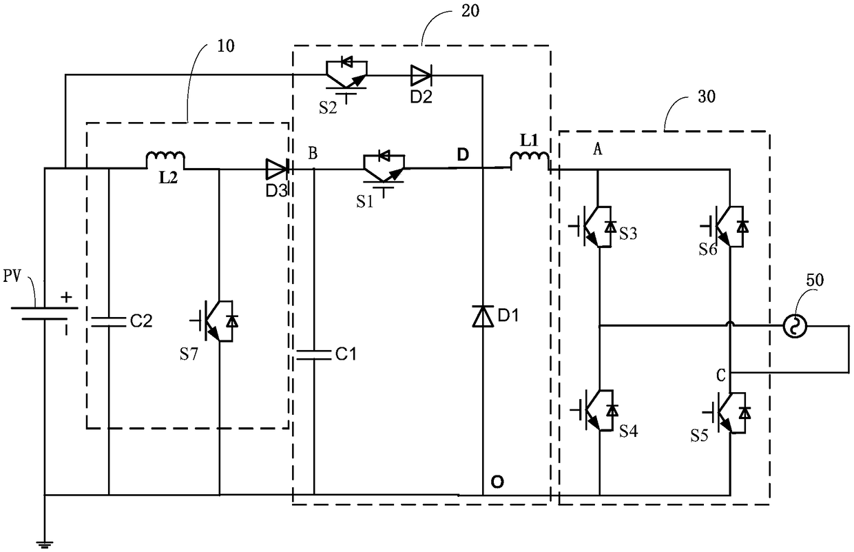
A solar inverter circuit comprises a boost circuit, a high-frequency chopper circuit, an inverter circuit and a controller. An input terminal of the boost circuit is connected with a positive electrode of a solar cell, and an output terminal of the boost circuit is connected with a first input terminal of the high-frequency chopper circuit. The first input terminal of the high-frequency chopper circuit is connected with the output terminal of the boost circuit, the second input terminal of the high-frequency chopper circuit is connected with the input terminal of the boost circuit, and the output terminal of the high-frequency chopper circuit is connected with the input terminal of the inverter circuit. The input end of the inverter circuit is connected with the output end of the high frequency chopper circuit, and the output end of the inverter circuit is connected with the mains. As that second switch tube is provided between the solar cell and the first inductance, that voltage ofthe solar cell is high than the mains voltage, the boost circuit is not required to boost the voltage of the solar cell and then supplied to the inverter circuit, but the pow of the solar cell is directly supplied to the inverter circuit through the second switch transistor, thereby improving the energy conversion efficiency.

Description

technical field [0001] The present application relates to the technical field of photovoltaic power generation, in particular to a solar inverter circuit. Background technique [0002] In the current photovoltaic inverter circuit, because the input voltage of the photovoltaic panel is an unstable voltage, many designs will add a boost voltage circuit to the photovoltaic input terminal to increase the input range of the photovoltaic inverter, but the inverter circuit is actually a buck circuit. Output, one up and one down makes the energy conversion efficiency of the system lower. [0003] In addition, in the photovoltaic inverter circuit, because the photovoltaic panel has a parasitic capacitance to the ground, in the traditional isolated inverter circuit, the solar cell will produce high-frequency fluctuations to the ground, resulting in excessive common-mode current, which is easy to cause leakage. Faults such as excessive current. Contents of the invention [0004] Th...

Claims


Application Information

Patent Timeline
IPC IPC(8): H02M7/5387H02M3/156H02M1/12
CPCH02M1/12H02M3/156H02M7/53871H02M1/123
Inventor 李晓锋吴良材丁永强
Owner 深圳古瑞瓦特新能源有限公司
Why Eureka
Try Eureka