Method for manufacturing circuit substrate alignment target

A circuit substrate and alignment target technology, which is applied in the direction of circuit board tool positioning, printed circuit manufacturing, printed circuit, etc., can solve the problems of difficult identification and easy filling of targets, so as to improve accuracy, improve target recognition rate, The effect of avoiding errors

Active Publication Date: 2020-05-12
SHENZHEN KINWONG ELECTRONICS
View PDF5 Cites 0 Cited by
  • Summary
  • Abstract
  • Description
  • Claims
  • Application Information

AI Technical Summary

Problems solved by technology

[0004] The purpose of the present invention is to provide a method for manufacturing a circuit substrate alignment target, which aims to solve the technical problem that the target is easy to be filled and difficult to identify in the prior art

Method used


Image

  • Method for manufacturing circuit substrate alignment target
  • Method for manufacturing circuit substrate alignment target
  • Method for manufacturing circuit substrate alignment target

Examples


Embodiment Construction

[0030] Embodiments of the present invention are described in detail below, examples of which are shown in the drawings, wherein the same or similar reference numerals designate the same or similar elements or elements having the same or similar functions throughout. The embodiments described below by referring to the figures are exemplary and are intended to explain the present invention and should not be construed as limiting the present invention.

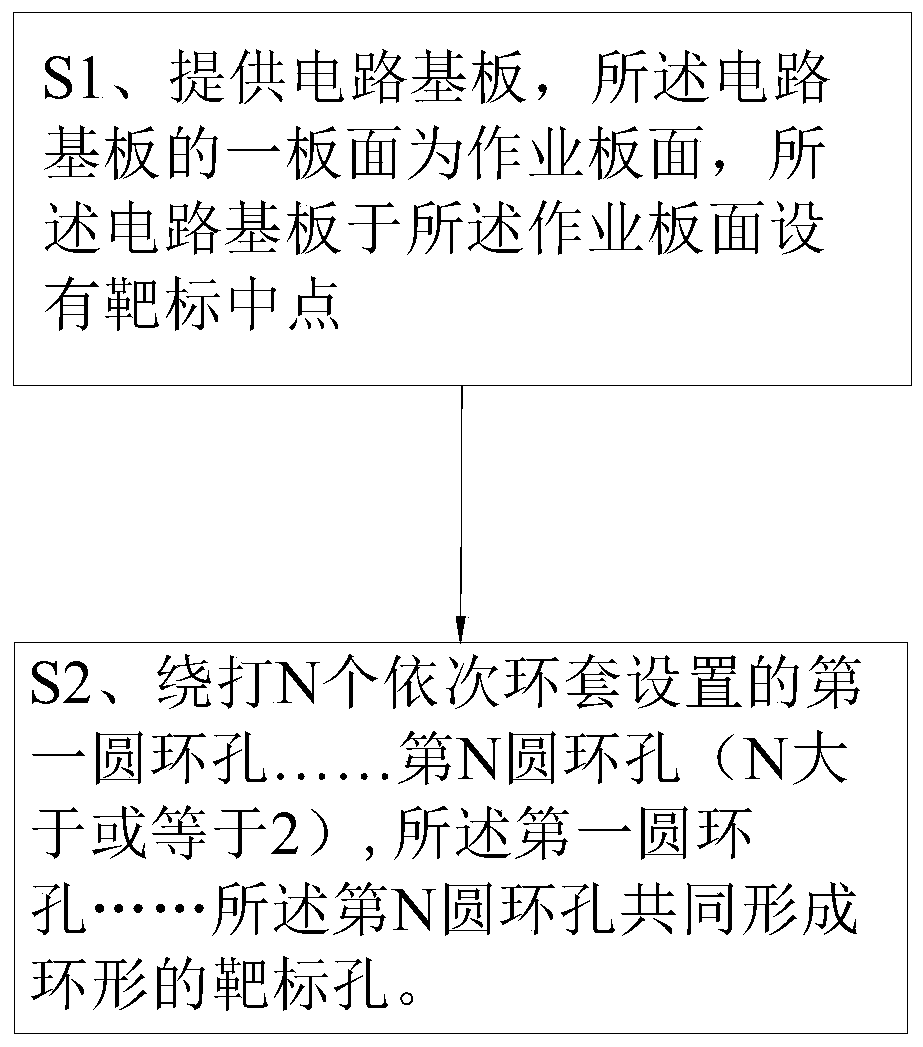
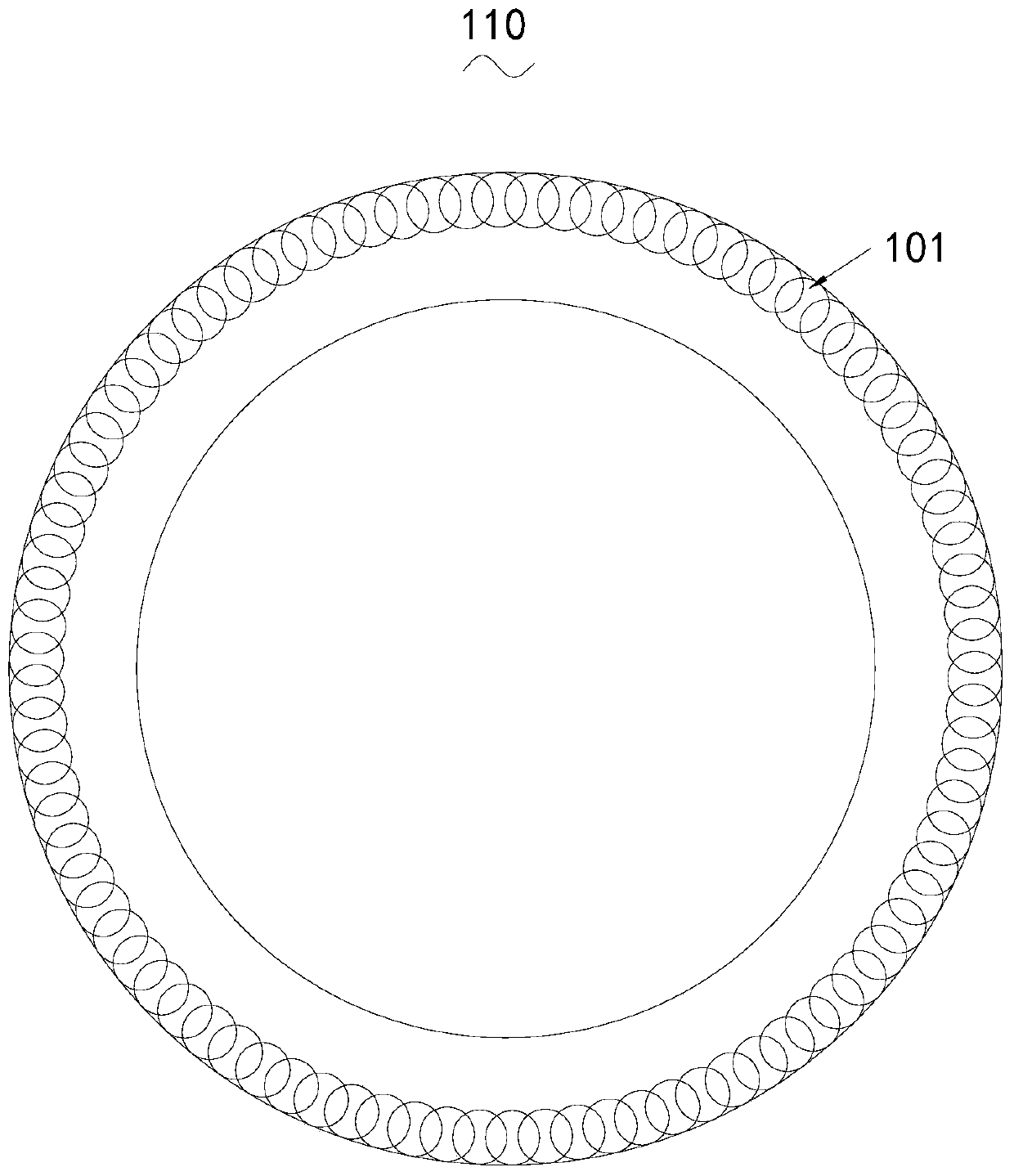
[0031] In addition, the terms "first"..."Nth" are used for descriptive purposes only, and cannot be interpreted as indicating or implying relative importance or implicitly specifying the number of indicated technical features. Thus, a feature defined as "first"..."Nth" may explicitly or implicitly include one or more of such features. In the description of the present invention, "plurality" means two or more, unless otherwise specifically defined.

[0032] In order to make the object, technical solution and advantages of the pre...


PUM


Abstract

A method for constructing an auto disturbance rejection torque prediction controller of switch reluctance BSG motor the current detection module and the angle detection module respectively collect thecurrent ik and the angle signal thetak at the time of k, the speed calculating module calculates the rotational speed omega k at the k time through the angle, inputting the collected current ik and angle signal thetak at time k into a torque prediction controller, the torque value at k+1 time is predicted by the torque predictive controller, A torque predictive controller outputs an optimal control vector Sg, The switching reluctance motor (SRM) is ensured to run by switching on and off of the power converter through the optimal control vector. The collected speed signal Omega k is inputted to the ADRC, and the reference speed is given. The reference torque Te given by the torque predictive controller is obtained by the ADRC. The invention adopts the torque predictive control, which can realize the rolling optimization and correction of the model, improve the accuracy of the model and increase the stability of the control, thereby reducing the torque ripple.

Description

technical field [0001] The invention belongs to the technical field of printed circuit boards, in particular to a method for manufacturing a circuit substrate alignment target. Background technique [0002] In the existing production of printed circuit boards, LDI (laser direct imaging, the Chinese full name is laser direct imaging technology) is used in the exposure process in the circuit board process. The difference from the traditional film contact exposure method is that the traditional exposure is irradiated by a mercury lamp The film transfers the image to the circuit board, while LDI uses laser scanning to directly image the circuit on the circuit board, and needs to be aligned with the target before imaging. [0003] With the development of circuit boards in the direction of miniaturization and high density, the accuracy of lithographic alignment of circuit boards is also getting higher and higher, and the alignment accuracy directly affects the quality of the subst...

Claims


Application Information

Patent Timeline
Patent Type & Authority Patents(China)
IPC IPC(8): H05K3/00
CPCH05K3/00H05K3/0008H05K3/0044
Inventor 肖安云王俊
Owner SHENZHEN KINWONG ELECTRONICS
Why Eureka
Try Eureka