Flowerpot with water supplement function

A function and flowerpot technology, applied in automatic watering devices, container cultivation, gardening, etc., can solve the problems of rapid evaporation, unfavorable seedling growth, and inability to protect seedlings from sun protection, and achieve the effect of preventing damage and avoiding the growth environment being too dark

Inactive Publication Date: 2019-01-25
何静雅
View PDF8 Cites 29 Cited by
  • Summary
  • Abstract
  • Description
  • Claims
  • Application Information

AI Technical Summary

Problems solved by technology

At present, most of the automatic water replenishment flower pots on the market are provided with a water storage chamber at the bottom of the pot body, and the water in the water storage chamber is sucked into the soil through a water-absorbing rope. The disadvantage of this water replenishment method is that the surface soil is difficult to Get sufficient water supply, especially when the plants planted in pots are small or in the seedling stage, the root system of the plants is still shallow, and the lack of water in the surfac

Method used


Image

  • Flowerpot with water supplement function
  • Flowerpot with water supplement function
  • Flowerpot with water supplement function

Examples


Example Embodiment

[0020] Example 1

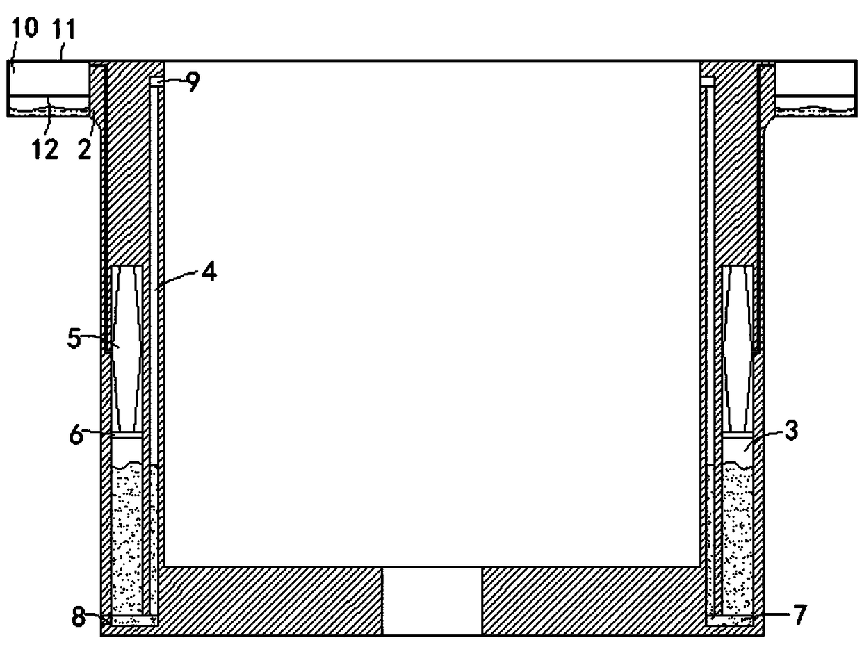
[0021] like figure 1 Shown, a kind of flower pot with replenishing water function, comprises pot body 1, pot edge 2 is arranged on the annular side wall of pot body 1, and the inner wall of pot body 1 is provided with a plurality of first chambers 3 and a plurality of second chambers. The chamber 4, the first chamber 3 and the second chamber 4 are arranged in one-to-one correspondence, the first chamber 3 is arranged in the basin body 1 between the second chamber 4 and the basin edge 2, so the first chamber 1 The top surface of the airbag 5 is provided with an airbag 5 that can only expand up and down. The side walls of the middle part of the airbag 5 are fixedly connected with the inner wall of the first chamber 3, and the first chamber 3 is slidingly and sealingly connected with a first arc-shaped piston plate 6. The upper end of an arc-shaped piston plate 6 is fixedly connected with the lower end of the air bag 5, wherein the air bag 5 is an elastic air ...

Example Embodiment

[0024] Example 2

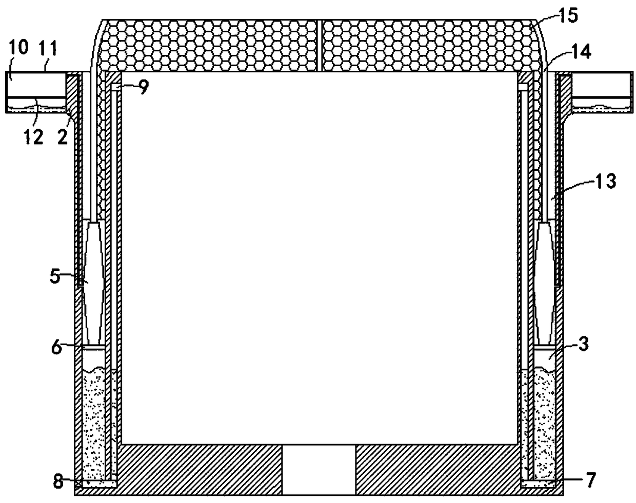
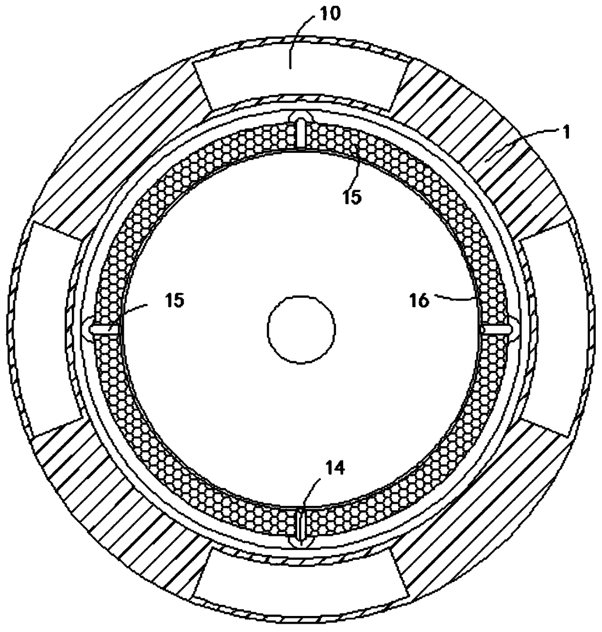
[0025] like Figure 2-6 As shown, the difference between this embodiment and Embodiment 1 is that: the upper surface of the basin body 1 is provided with an annular groove 13, and the annular groove 13 is communicated with a plurality of first chambers 3, and the annular groove A plurality of rubber rods 14 are arranged in the groove 13, the lower ends of the rubber rods 14 are fixedly connected with the upper end of the airbag 5, the side walls of the plurality of rubber rods 14 are fixedly connected with a sunscreen 15, and the plurality of rubber rods 15 is sleeved with the same rubber band 16, and the rubber band 16 is located above the sunscreen net 15. It is worth mentioning that both the rubber rod 15 and the sunscreen net 17 are elastic, so that they can shrink in the annular groove 13.

[0026] The present invention can drive the rubber rod 14 to move upward through the expansion volume of the air bag 5, and can drive the sun protection net 15 to r...


PUM


Abstract

The invention belongs to the technical field of flowerpots, in particular to a flowerpot with a water supplement function. The flowerpot comprises a pot body, a pot edge is arranged on the circular side wall of the pot body, a plurality of first chambers and a plurality of second chambers are arranged on the inner wall of the pot body, the first chambers are in one-to-one corresponding to the second chambers, the first chambers are arranged in the pot body among the second chambers and the pot edge, air bags arranged on the top surfaces of the first chambers and can only vertically expand andcontract, the middle side walls of the air bags are fixedly connected with the inner walls of the first chambers, first arc-shaped piston plates are slidably and hermetically connected in the first chambers, the upper ends of the first arc-shaped piston plates are fixedly connected with the lower ends of the air bags, a water spraying opening is formed in the inner wall of one end, far away from the pot edge, of each second chamber, the water spraying openings approach to top surfaces of the second chambers, and third chambers are arranged on the inner wall of the pot body. The flowerpot can automatically supplement water for upper soil in high temperature weather of sun shine and has a sunscreen effect on planted young seedlings.

Description

technical field [0001] The invention belongs to the technical field of flower pots, in particular to a flower pot with water replenishment function. Background technique [0002] The self-watering flowerpot is a container that automatically supplies water to the soil in the flowerpot. At present, most of the automatic water replenishment flower pots on the market are provided with a water storage chamber at the bottom of the pot body, and the water in the water storage chamber is sucked into the soil through a water-absorbing rope. The disadvantage of this water replenishment method is that the surface soil is difficult to Get sufficient water supply, especially when the plants planted in pots are small or in the seedling stage, the root system of the plants is still shallow, and the lack of water in the surface soil will easily affect the normal growth of the plants; at the same time, many potted plants cannot withstand strong sunlight Direct sunlight, especially for plant...

Claims


Application Information

Patent Timeline
IPC IPC(8): A01G9/02A01G27/02A01G13/02
CPCA01G9/02A01G13/0243A01G27/02
Inventor 何静雅
Owner 何静雅
Why Eureka
Try Eureka