Metallurgical method utilizing separation device

A technology for separating equipment and space, applied in the field of metallurgy, can solve the problems of rough product surface, waste cost, affect product performance, etc., and achieve the effect of increasing grinding effect, reducing control system and diversifying functions.

Inactive Publication Date: 2019-01-25
宁波奉化威顿机械有限公司
View PDF0 Cites 2 Cited by
  • Summary
  • Abstract
  • Description
  • Claims
  • Application Information

AI Technical Summary

Problems solved by technology

[0002] With the advancement of science and technology, powder metallurgy technology is constantly improving, and powder metallurgy is the process technology for producing metal powder or using metal powder as raw material, forming and sintering, manufacturing metal materials, composite materials and various types of products, and powder Metallurgy also has high requirements for the particles of raw material powder. If the particles are too large, the surface of the product will be rough, which will affect the quality of the product, and the bonding force between the particles will also deteriorate, which will affect the performance of the product. Traditional grinding and separation The device is separated, the grinding effect is poor, and the separation equipment is too simple, that is, it is screened through a separate screen, which can only be used for materials with one particle size, and it is difficult to change according to actual needs. Moreover, the traditional separation device It is easy to block the material, and it needs to be shut down for maintenance in the middle, so it cannot be used for a long time, and a lot of cost is wasted

Method used


Image

  • Metallurgical method utilizing separation device
  • Metallurgical method utilizing separation device
  • Metallurgical method utilizing separation device

Examples


Embodiment Construction

[0018] The following will clearly and completely describe the technical solutions in the embodiments of the present invention with reference to the accompanying drawings in the embodiments of the present invention. Obviously, the described embodiments are only some, not all, embodiments of the present invention. Based on the embodiments of the present invention, all other embodiments obtained by persons of ordinary skill in the art without making creative efforts belong to the protection scope of the present invention.

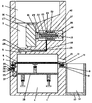
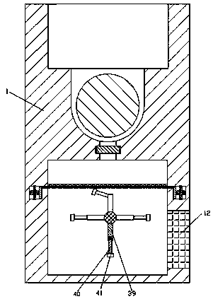
[0019] see Figure 1-3 , an embodiment provided by the present invention: a metallurgical method using a separation device, the separation device includes a fixed housing 1, wherein, the upper side of the fixed housing 1 is provided with a storage tank 2 with an upward opening A grinding space 3 is arranged on the left side of the lower end wall of the storage tank 2, a grinding device is arranged inside the right end wall of the grinding space 3, and a separa...


PUM


Abstract

The invention discloses a metallurgical method utilizing a separation device. The metallurgical method comprises a fixed housing, wherein the upper side of the inside of the fixed housing is providedwith a material storage tank with an upward opening, the left side of the lower end wall of the material storage tank is provided with a grinding space, a grinding device is arranged in the right endwall of the grinding space, the lower side of the inside of the fixed housing is provided with a separation space, the inner wall of a discharging hole is provided with a closing device in linkage with the grinding device, the upper side of the inside of the separation space is provided with a first filter screen, and the lower side of the inside of the separation space is provided with a knockingdevice. In work, the grinding effect of the device is improved, accordingly the requirement for powder grains in the sintering process is met, a control system is omitted through linkage and cooperation of the devices, the cost of the devices is reduced, the requirement for filtering different grains is met, the functions of the device is more diversified, and the phenomenon can be prevented thatgrains are clamped in filter holes and accordingly device blockage is caused.

Description

technical field [0001] The invention relates to the field of metallurgy, in particular to a metallurgical method utilizing separation equipment. Background technique [0002] With the advancement of science and technology, powder metallurgy technology is constantly improving, and powder metallurgy is the process technology for producing metal powder or using metal powder as raw material, forming and sintering, manufacturing metal materials, composite materials and various types of products, and powder Metallurgy also has high requirements for the particles of raw material powder. If the particles are too large, the surface of the product will be rough, which will affect the quality of the product, and the bonding force between the particles will also deteriorate, which will affect the performance of the product. Traditional grinding and separation The device is separated, the grinding effect is poor, and the separation equipment is too simple, that is, it is screened through...

Claims


Application Information

Patent Timeline
Patent Type & Authority Applications(China)
IPC IPC(8): B22F9/04
CPCB22F9/04B22F2009/041
Inventor 陈光达
Owner 宁波奉化威顿机械有限公司
Why Eureka
Try Eureka