Electronic paper laminating equipment

A technology of laminating equipment and electronic paper, applied in the directions of instruments, object supply, and sending objects, etc., can solve the problems of disrupting the normal operation of the production line, large adhesion force between the substrate and the roller, and high error rate of lamination operation, so as to shorten the production time. Cycle time, improve production efficiency, reduce the effect of error rate

Active Publication Date: 2021-12-07
张家港马提亚科技有限公司
View PDF13 Cites 0 Cited by
  • Summary
  • Abstract
  • Description
  • Claims
  • Application Information

AI Technical Summary

Problems solved by technology

[0003] The existing electronic paper lamination equipment mainly has the following technical defects: First, the traditional lamination method requires manual auxiliary cooperation, which leads to the extension of the entire production cycle and low production efficiency. At the same time, the semi-automatic method requires investment The safety management cost of a large number of personnel will increase the production cost; second, if the roller and the conveyor belt are used to cooperate, the substrate and the roller will have too much adhesion force during lamination, which will cause the substrate and the roller to be unable to separate automatically, causing confusion The normal operation of the entire production line leads to the problem of high error rate in lamination operation

Method used


Image

  • Electronic paper laminating equipment
  • Electronic paper laminating equipment
  • Electronic paper laminating equipment

Examples


Embodiment

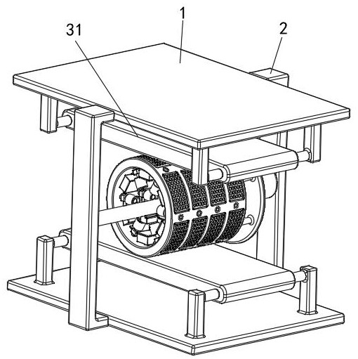
[0040] see Figure 1-6 , a kind of electronic paper pasting equipment, comprising a fixed plate 1, a fixed frame 2, a bonding device 3, a magnetic device 4 and a suction device 5, the left and right sides of the fixed plate 1 are fixedly connected with the fixed frame 2, and the fixed plate 1 is about There are two symmetrically arranged upper and lower sides of the fixed frame 2, a fitting device 3 is arranged between the two fixing plates 1, a magnetic device 4 is arranged at the axial inner center of the fitting device 3, and a suction device 5 is fixedly installed on the fitting on device 3;

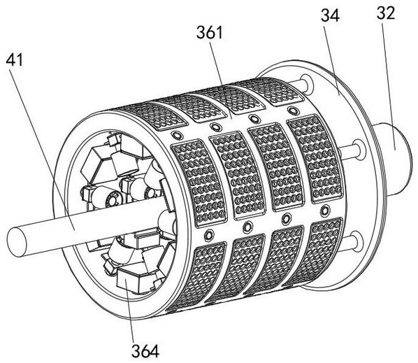
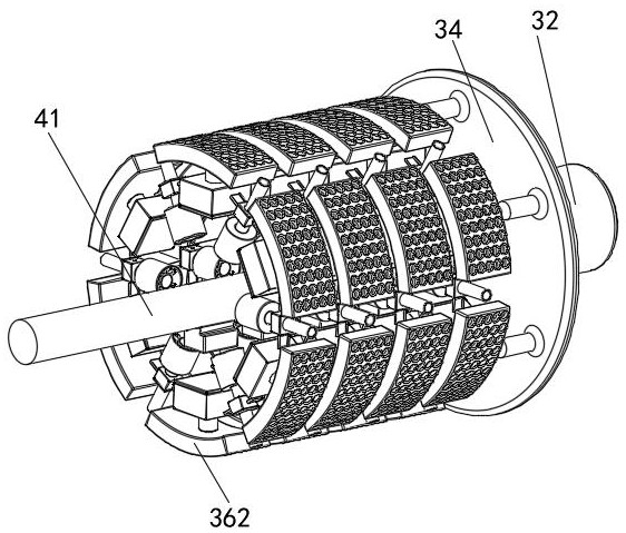
[0041]Laminating device 3 comprises conveyer belt mechanism 31, first motor 32, rotating shaft 33, rotating disk 34, branch bar 35 and roller device 36, and fixed plate 1 is connected with conveyer belt mechanism 31 by being fixedly connected with connecting block and rotatably connected, and the left side of fixed mount 2 The side is fixedly connected with a first motor 32, the lef...


PUM


Abstract

The invention discloses electronic paper laminating equipment. The equipment comprises a fixing plate, a fixing frame, a laminating device, a magnetic device and a suction device, the fixing plate is rotationally connected with a conveying belt mechanism by being connected with a connecting block, the left side surface of the fixing frame is fixedly connected with a first motor, the left side of the first motor is rotationally connected with a rotating shaft, the left side of the rotating shaft is fixedly connected with a rotating disc, the left side of the rotating disc is fixedly connected with a branch rod, and the left side of the branch rod is fixedly provided with a roller device. According to the electronic paper laminating equipment, under the matching effect of a strip roller, conveyor belt mechanisms on the upper side and the lower side and the first motor, the purpose that manual auxiliary matching is not needed in a laminating mode is achieved, the effect of full-automatic operation is achieved, the whole manufacturing period is shortened, the production efficiency is improved, and meanwhile, the problem that the manufacturing cost is increased due to the fact that a large amount of personnel safety management cost needs to be invested in a semi-automatic mode is solved.

Description

technical field [0001] The invention relates to the technical field of electronic paper manufacturing, in particular to electronic paper bonding equipment. Background technique [0002] E-paper is a kind of display that is as thin as paper, soft and rewritable. Its display effect is close to that of natural paper, thereby effectively avoiding reading fatigue. E-paper is made by superimposing electronic ink and two substrates of. [0003] The existing electronic paper lamination equipment mainly has the following technical defects: First, the traditional lamination method requires manual auxiliary cooperation, which leads to the extension of the entire production cycle and low production efficiency. At the same time, the semi-automatic method requires investment The safety management cost of a large number of personnel will increase the production cost; second, if the roller and the conveyor belt are used to cooperate, the substrate and the roller will have too much adhesion...

Claims


Application Information

Patent Timeline
Patent Type & Authority Applications(China)
IPC IPC(8): B65H37/04B65H5/02B65H5/22G09F9/37
CPCB65H37/04B65H5/025B65H5/226G09F9/37B65H2701/1131
Inventor 奥飚
Owner 张家港马提亚科技有限公司
Why Eureka
Try Eureka