Fixed-length flying saw sawing method and sawing device for achieving same

A sawing and flying sawing technology, which is applied in the direction of metal sawing equipment, metal processing equipment, sawing machine accessories, etc., can solve the problems of unsatisfactory sawing accuracy, reduced service life of saw blades, and fluctuations in material moving speed, etc., to achieve Avoid damage to the sawing mechanism, improve positioning accuracy, and achieve the effect of organic combination

Pending Publication Date: 2019-01-25
广东科莱博科技有限公司
View PDF0 Cites 2 Cited by
  • Summary
  • Abstract
  • Description
  • Claims
  • Application Information

AI Technical Summary

Problems solved by technology

[0003] 1. The flying saw method uses the flying saw trolley to drive the sawing mechanism to move at the moving speed of the material, and the following speed of the flying saw trolley is dynamically controlled by the material moving speed measured by the encoder; when the sawing mechanism is driven by the flying saw trolley to move, saw The material is sawed by the cutting mechanism; however, due to the instantaneous speed fluctuation (speed inconsistency) of the two drawing trolleys in the cam-type combined drawing equipment when drawing alternately, the moving speed of the material fluctuates; due to the influence on the moving speed of the material There is a time difference between detection and response, so it is difficult to synchronize the speed of the flying saw trolley when the moving speed of the material fluctuates; if the sawing mechanism just drops the saw at the moment of speed fluctuation, it will cause uneven sawing of the material and zoom in on the color, reducing the service life of the saw blade , and even break the saw blade
[0004] 2. The follow-up sawing method adopts the saw car to hold the material tightly, and uses the movement of the material as the driving force of the saw car. When sawing, there is no relative movement between the saw car and the material, the saw edge is neat, and the loss of the saw blade is small; but because the saw car is stationary The state hugs the material in the moving state, and it is easy to cause a large positioning error between the saw blade and the preset material sawing position due to slight time errors; therefore, the sawing accuracy is not ideal. In addition, the follow-up saw is generally used for low-speed moving materials sawing, unable to adapt to the sawing of high-speed moving materials

Method used


Image

  • Fixed-length flying saw sawing method and sawing device for achieving same
  • Fixed-length flying saw sawing method and sawing device for achieving same
  • Fixed-length flying saw sawing method and sawing device for achieving same

Examples


Embodiment 1

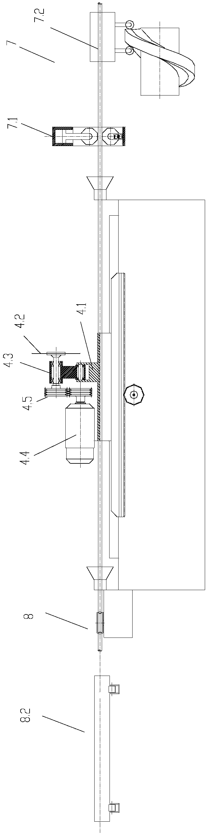
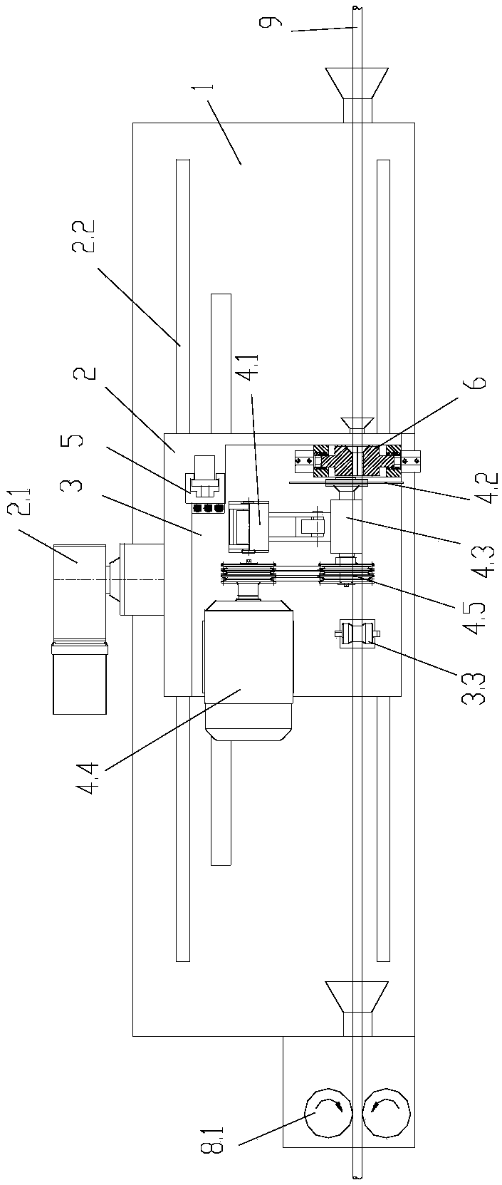
[0037] This embodiment is a fixed-length flying saw sawing method, which includes a speed-tracking process and a synchronous sawing process; The cutting mechanism 4 moves with acceleration and deceleration until the moving trolley 2 is synchronized with the moving speed of the material and the sawing mechanism 4 is positioned between the preset sawing position of the material; during the acceleration and deceleration process of the moving trolley 2, the floating car body 3 passes through the floating positioning structure 5 is relatively fixed with the mobile trolley 2, and the mobile trolley 2 moves synchronously with the floating car body 3 and the sawing mechanism 4;

[0038] The synchronous sawing process refers to: after the mobile car 2 is synchronized with the moving speed of the material, the mobile car 2 continues to drive the floating car body 3 and the sawing mechanism 4 to move; the floating car body 3 and the material are fixed to realize the floating car body 3 i...

Embodiment 2

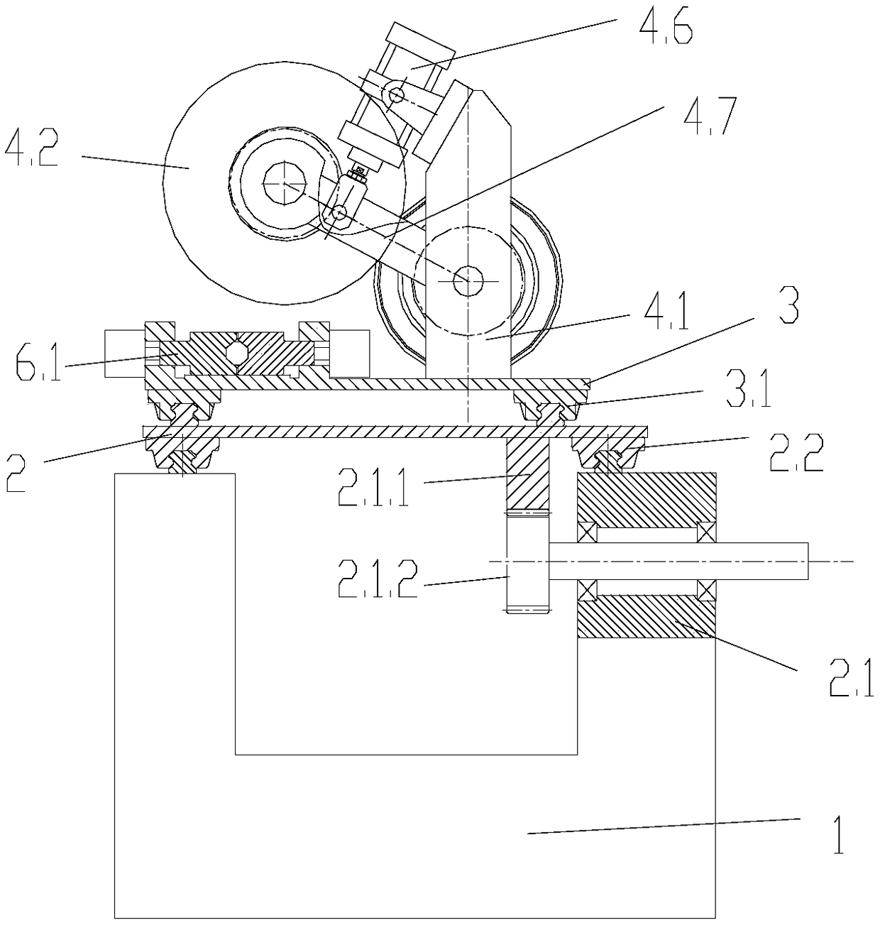
[0053] The difference between the sawing method of the fixed-length flying saw in this embodiment and the first embodiment is that in this embodiment, when the moving speed of the material fluctuates, the floating positioning structure moves due to the push-pull force exerted by the material on the floating car body, which means: The floating positioning structure is an elastic component, and the elastic component exerts a preset support force on the moving trolley and the floating car body in the moving direction of the material. When the moving speed of the material fluctuates, the external force ≥ the preset supporting force on the floating positioning structure, the floating car body passes The floating positioning structure can move relative to the mobile car; when the floating positioning structure is not subjected to external force or the external force is less than the preset support force, the floating positioning structure makes the mobile car and the floating car rela...


PUM


Abstract

The invention provides a fixed-length flying saw sawing method which is characterized by comprising a speed chasing process and a synchronous sawing process. The speed chasing process means that a moving trolley is adopted to carry a floating car body and a sawing mechanism set on the floating car body to accelerate and decelerate; the floating car body is relatively fixed with the moving trolleythrough a floating positioning structure, and the moving trolley synchronously accelerates and decelerates with the floating car body and the sawing mechanism. The synchronous sawing process means that after the moving trolley and a material are synchronous in moving speed, the moving trolley keeps driving the floating car body and the sawing mechanism to move; the floating car body and the material are fixed to achieve the linkage between the floating car body and the material; in the process that the sawing mechanism always moves synchronously with the material, the sawing mechanism cuts thematerial. According to the method, the sawing precision can be improved, the saw bite flatness can be improved, damage to the sawing mechanism is avoided, and the sawing method is suitable for both high speed moving sawing and low speed moving sawing. The invention also provides a sawing device for achieving the method.

Description

technical field [0001] The invention relates to the technical field of sawing with a flying saw to a fixed length, and more specifically, to a sawing method with a flying saw to a fixed length and sawing equipment for realizing the method. Background technique [0002] During metal processing, it is often necessary to cut metal materials. For example, after the materials are drawn, straightened, cut and polished by the combined drawing equipment, the materials need to be sawed. There are two kinds of existing sawing methods, one is a flying saw, and the other is a moving saw. Both methods have disadvantages: [0003] 1. The flying saw method uses the flying saw trolley to drive the sawing mechanism to move at the moving speed of the material, and the following speed of the flying saw trolley is dynamically controlled by the material moving speed measured by the encoder; when the sawing mechanism is driven by the flying saw trolley to move, saw The material is sawed by the...

Claims


Application Information

Patent Timeline
Patent Type & Authority Applications(China)
IPC IPC(8): B23D45/20B23D59/00
CPCB23D45/20B23D59/00
Inventor 陈朝伟张荣欣王箫刘盼
Owner 广东科莱博科技有限公司
Why Eureka
Try Eureka