Motor-driven pressing machine

A motor-driven, pressing machine technology, applied to printing machines, rotary printing machines, printing, etc., can solve the problems of large cylinder volume and air consumption, bulky pressing machine, and uneconomical problems, so as to save space and save Transportation cost, compact structure effect

Pending Publication Date: 2019-01-25
阮文仁
View PDF2 Cites 3 Cited by
  • Summary
  • Abstract
  • Description
  • Claims
  • Application Information

AI Technical Summary

Problems solved by technology

[0002] Pressing machine is mainly used for the transfer printing of clothing surface pattern, as announcement is: CN204417889U discloses a kind of pneumatic pressing machine, comprises machine base and pressing device, is respectively installed on the lift cylinder and control device on the machine base, described The pressing device includes an upper pressing plate and a lower pressing plate fixed on the machine base; the lifting cylinder controls the upper pressing plate to move up and down, and the upper pressing plate includes a pressing plate frame with a mounting cavity, a heating plate And the pressing plate, the inner top surface of the pressing plate frame is provided with a return spring, the heating plate is located in the installation cavity and connected with the return spring in conflict, the pressing plate is fixed on the heating plate, this pneumatic pressing machine The movement of the upper pressing plate is driven by the lifting movement of the cylinder. Since the upper pressing plate only touches the lower pressing plate for a short stroke, the cylinder needs to provide a larger push. Most of the strokes are empty, but in order to meet the pressure of the pressing machine The need for pressure requires the use of a cylinder with a large stroke and high pressure, so that the volume and air consumption of the cylinder will be large, so the use of a pressing machine is bulky and energy-consuming, which is not economical.
[0003] For this reason, the applicant has designed a labor-saving pressing machine. As the announcement number, CN106515204A discloses a pressing machine, including a frame, a pressing device and a controller, and the described pressing device includes an upper pressing plate and The lower pressing ironing plate is fixed on the frame, the upper pressing ironing plate is hinged on one end of a driving lever, the middle part of the driving lever is pivotally connected to the frame, and the other end of the driving lever is connected to the frame The stroke cylinder is connected between them, and the moment length of the power arm from the hinge point of the stroke cylinder and the drive lever to the pivot is less than the length of the resistance arm from the hinge point of the upper pressing plate and the drive lever to the pivot; between the upper press plate and the frame A pressure device is also provided between them. When the stroke cylinder drives the upper pressing plate to approach or touch the lower pressing plate, the pressure device provides the pressure for the upper pressing plate during pressing. The pressure device and the stroke cylinder are controlled by the controller. ;The pressing machine adopts the principle of segmented driving torque amplification, but the above-mentioned pressing machines are all driven by cylinders, and the cylinders also need to be equipped with air compressors, and the air compressors are noisy when they work, and their use is limited

Method used


Image

  • Motor-driven pressing machine
  • Motor-driven pressing machine
  • Motor-driven pressing machine

Examples


Embodiment Construction

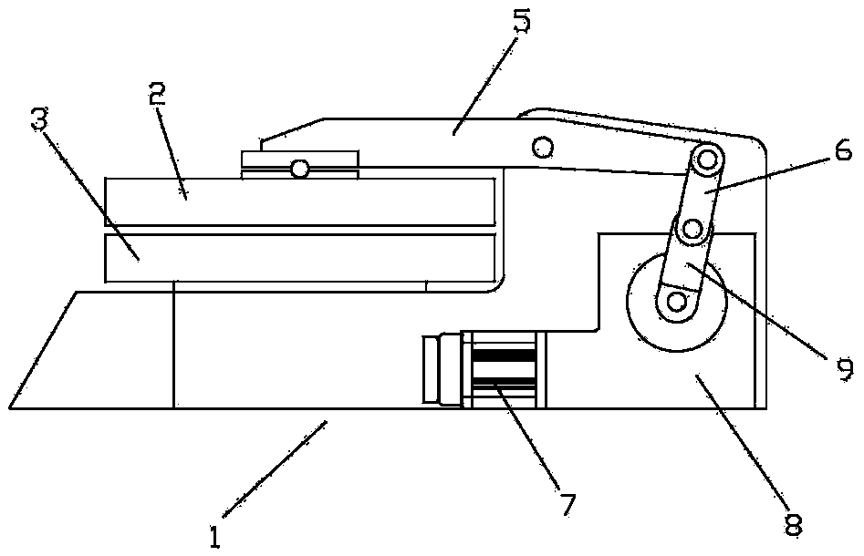
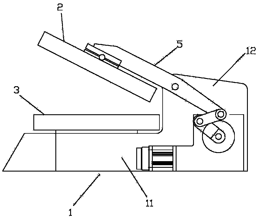
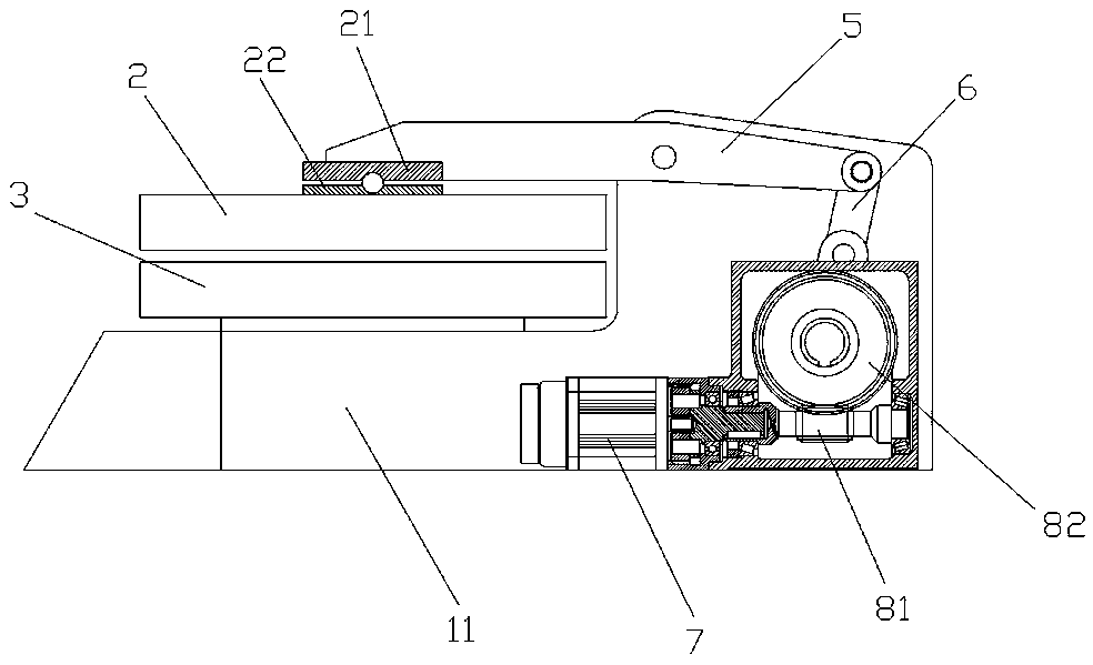
[0015] Such as Figure 1-4 As shown, a motor-driven pressing machine includes a base 1, a pressing device and a controller, the pressing device includes an upper pressing plate 2 and a lower pressing plate 3, and the base 1 includes a base 11 and connecting seat 12, the connecting seat 12 is set on the top of the rear side of the base 11, the lower pressing plate 3 is fixed on the top of the front side of the base 11, and the upper pressing plate 2 is set on the front end of the rocker arm 5 The middle part of the rocker arm 5 is pivotally connected to the connecting seat 12, and the upper pressing plate 2 is fixed on the front end of the rocker arm 5 through the upper connecting plate 21 and the lower connecting plate 22 pivotally connected to each other; the rear end of the rocking arm 5 The part is connected with the drive mechanism through the connecting rod 6; the drive mechanism includes a DC motor 7, a worm gear reducer 8 and an output arm 9, the DC motor 7 is provided ...


PUM


Abstract

The invention relates to a motor-driven pressing machine. The motor-driven pressing machine comprises a machine base, a pressing device and a controller, wherein the pressing device comprises an upperpressing plate and a lower pressing plate, the lower pressing plate is fixed to the machine base, the middle of a rocker is in pivot connection with the machine base, the upper pressing plate is arranged at the front end of the rocker, and the rear end of the rocker is connected with a driving mechanism through a connection rod. The driving mechanism comprises a driving motor, a worm reducer andan output arm, the driving motor is arranged on the machine base, the output end of the driving motor is connected with a worm rod of the worm reducer, the lower end of the output arm is fixedly connected with a worm output shaft of the worm reducer, the upper end of the output arm is hinged to the lower end of the connection rod, the upper end of the connection rod is hinged to the rear end of the rocker, and the controller controls the driving motor and the upper and lower pressing plates to work. The motor-driven pressing machine is driven by the direct current motor, and the motor-driven pressing machine has the advantages that the structure is more compact, the shape is more attractive, the cost is reduced, and more convenience is brought.

Description

technical field [0001] The invention relates to a pressing machine, in particular to a motor-driven pressing machine. Background technique [0002] Pressing machine is mainly used for the transfer printing of clothing surface pattern, as announcement is: CN204417889U discloses a kind of pneumatic pressing machine, comprises machine base and pressing device, is respectively installed on the lift cylinder and control device on the machine base, described The pressing device includes an upper pressing plate and a lower pressing plate fixed on the machine base; the lifting cylinder controls the upper pressing plate to move up and down, and the upper pressing plate includes a pressing plate frame with a mounting cavity, a heating plate And the pressing plate, the inner top surface of the pressing plate frame is provided with a return spring, the heating plate is located in the installation cavity and connected with the return spring in conflict, the pressing plate is fixed on the...

Claims


Application Information

Patent Timeline
IPC IPC(8): B41F16/00B41F16/02
CPCB41F16/0046B41F16/02B41P2219/12
Inventor 阮文仁
Owner 阮文仁
Why Eureka
Try Eureka