Retractable fork device

A telescopic fork and sprocket technology, applied in the direction of lifting devices, etc., can solve the problems of high precision requirements, time-consuming and labor-consuming, and weak system stability, and achieve the reduction of processing and manufacturing precision requirements and installation and coordination precision requirements, The effect of reducing the complexity and weight of the structure and improving the efficiency of production operations

Pending Publication Date: 2019-01-25
CHANGSHA HUAHENG ROBOT SYST
View PDF15 Cites 3 Cited by
  • Summary
  • Abstract
  • Description
  • Claims
  • Application Information

AI Technical Summary

Problems solved by technology

[0003] One is that the multi-stage forks of the existing telescopic forks, especially between other forks except the end forks, generally adopt a gear-matched transmission mode, which requires the configuration of multiple mutually cooperating gear transmission systems , the transmission coordination between the gears requires extremely high precision, which leads to the high precision of the processing and manufacturing of the gear components, and the second requires high installation and coordination precision of multiple gear transmission systems. , It also needs frequent inspection and maintenance to maintain extremely high transmission accuracy, resulting in time-consuming, labor-intensive, and high maintenance costs
[0004] The second is that the multi-stage telescopic fork itself has a complex structure, and the use of multiple gear transmission systems that cooperate with each other further leads to a very complicated structure of the telescopic fork, which is prone to maintenance problems during operation, causing the system to stop working and affecting work efficiency.
And this configuration also causes the weight of the equipment to be extremely heavy, which is not conducive to the transportation and movement of the equipment
[0005] Third, many existing telescopic forks can only achieve three-level telescopic expansion, and the telescopic method is not flexible enough, the system stability is not strong, and it cannot be well adapted to the current operating requirements.

Method used


Image

  • Retractable fork device
  • Retractable fork device
  • Retractable fork device

Examples


Embodiment Construction

[0025] The present invention will be further described in detail below in conjunction with the accompanying drawings and specific embodiments.

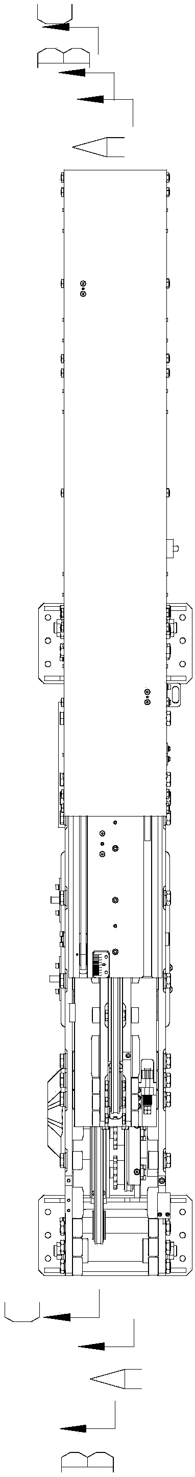
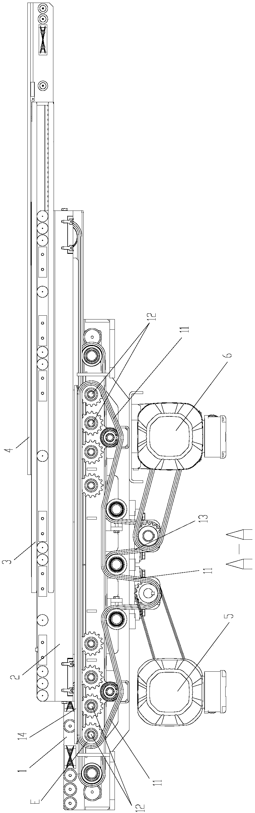
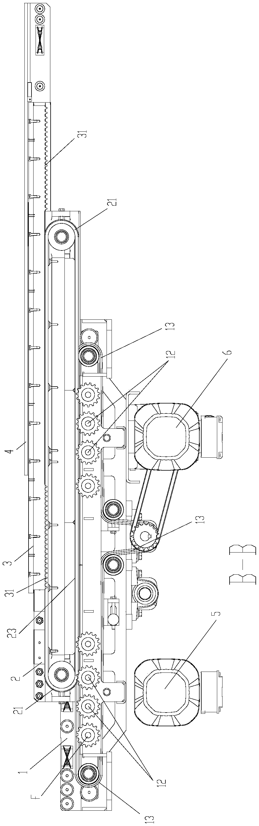
[0026] like Figure 1 to Figure 4 As shown, the present invention provides a telescopic fork device, comprising a first-level fork 1, a second-level fork 2, a third-level fork 3 and a fourth-level fork 4 arranged in sequence, and the first-level fork 1 is provided with a plurality of fixing components ( not shown in the figure), for fixing the device on other equipment (such as lifting, mobile platform). The third-stage fork 3 and the fourth-stage fork 4 are linked, and the first-stage fork 1 is provided with a circle of the first sprocket assembly 11 (it can be expected that the sprocket assembly must include a plurality of driven wheels and a circle wound on the plurality of driven wheels. chain). A circle of second sprocket assembly 21 is provided on the secondary fork 2 (it can be expected that the sprocket assembly must also in...


PUM


Abstract

The invention discloses a retractable fork device. The retractable fork device comprises a first-section fork, a second-section fork, a third-section fork and a fourth-section fork which are sequentially arranged cooperatively, wherein the first-section fork is provided with a circle of first chain wheel assembly, the second-section fork is provided with a circle of second chain wheel assembly, the first-section fork is provided with multiple double-gear driven chain wheels in the length direction, each double-gear driven chain wheel is provided with two parallelly arranged gear discs used formaking the two gear discs to respectively engaged with the first chain wheel assembly and the second chain wheel assembly, the first chain wheel assembly is connected with a first driving mechanism and used for driving the second chain wheel assembly to rotate when the first driving mechanism drives the first chain wheel assembly to rotate, and the third-section fork is provided with a row of first chain racks engaged with the second chain wheel assembly in the length direction. The retractable fork device has the advantages of being simple and compact in structure, easy to manufacture and maintain, strong in overall stability, high in safety and capable of achieving four-section telescoping.

Description

technical field [0001] The invention mainly relates to the field of logistics conveying equipment, in particular to a telescopic fork device. Background technique [0002] The telescopic fork is the main mechanism for accessing items, with automatic telescopic function, it is directly assembled on the stacker (lifting, moving platform), the stacker walks through the lanes between the shelves, and completes the work of automatic access to items ( Can also be assembled on a fixed workbench). There are following several technical problems in existing telescopic pallet fork: [0003] One is that the multi-stage forks of the existing telescopic forks, especially between other forks except the end forks, generally adopt a gear-matched transmission mode, which requires the configuration of multiple mutually cooperating gear transmission systems , the transmission coordination between the gears requires extremely high precision, which leads to the high precision of the processing ...

Claims


Application Information

Patent Timeline
Patent Type & Authority Applications(China)
IPC IPC(8): B66F9/12B66F9/075
CPCB66F9/07504B66F9/12
Inventor 邹涛谭坚羽潘树
Owner CHANGSHA HUAHENG ROBOT SYST
Why Eureka
Try Eureka