Clamping-plate support of hub-type joint net rack

A splint type, node technology, applied in the direction of architecture, building structure, etc., can solve the problem that the anti-risk ability needs to be improved

Pending Publication Date: 2019-01-25
HUADIAN HEAVY IND CO LTD
View PDF5 Cites 2 Cited by
  • Summary
  • Abstract
  • Description
  • Claims
  • Application Information

AI Technical Summary

Problems solved by technology

[0004] However, the original support of the hub node is not subject to shear force on the screw, and the anti-risk ability needs to be improved

Method used


Image

  • Clamping-plate support of hub-type joint net rack
  • Clamping-plate support of hub-type joint net rack

Examples


Embodiment 1

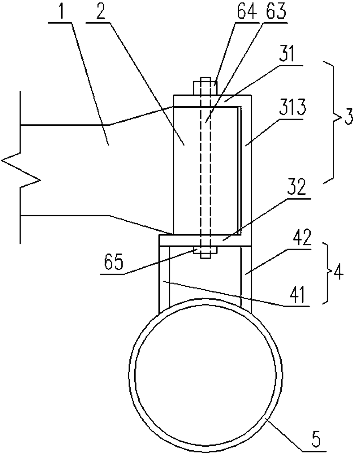
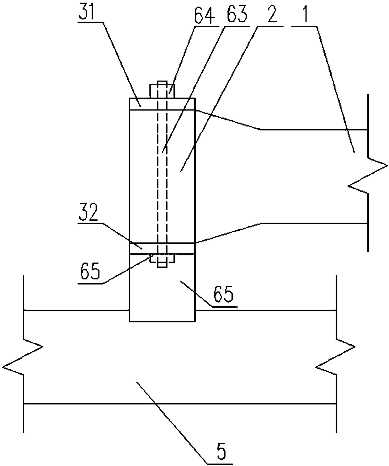
[0038] Such as Figure 1-2 As shown, the present embodiment provides a splint-type support of a hub-type node network frame, including: a holding part 3 having a fixed end plate and a first blocking end plate 31 arranged in parallel on one side of the fixed end plate 313 and The second blocking end plate 32, a positioning groove suitable for inserting the hub node 2 is enclosed between the two blocking end plates and the fixed end plate, and the hub node 2 is inserted into the positioning groove to the limit position, and the two blocking end plates form a blocking and clamping structure at both ends of the hub node 2 in the axial direction; the locking assembly includes sequentially passing through the first The blocking end plate 31, the hub node 2, the penetrating piece of the second blocking end plate 32, and the two ends of the penetrating piece are adapted to limit the axis of the penetrating piece along the hub node 2. A locking member to be displaced; a connecting mem...


PUM


Abstract

The invention provides a clamping-plate support of hub-type joint net rack. The technical problem that a threaded rod is not subjected to shearing force is solved. The clamping-plate support in the technical scheme comprises a keeping part, a locking assembly and a connecting piece, wherein the keeping part is provided with a fixing end plate, a first blocking end plate and a second blocking end plate, the first blocking end plate and the second blocking end plate are arranged on one side face of the fixing end plate in parallel, and a positioning groove suitable for imbedding into a hub jointis defined by the portion between the two blocking end plates and the fixing end plate; the locking assembly comprises a penetrating piece sequentially penetrating the first blocking end plate, the hub joint and the second blocking end plate in the axis direction of the hub joint and locking pieces arranged at the two ends of the penetrating piece; the connecting piece is suitable for connectingthe keeping part on a to-be-connected object. Clamping-plate blocking in the prior art is replaced with a clamping-type blocking structure, rigid connection is carried out between blocking, the wholestructural strength of the support is enhanced, the penetrating piece can bear the shearing resistance of the certain degree, and the structural strength of the support is greatly enhanced.

Description

technical field [0001] The invention relates to the technical field of large-span steel structures, in particular to a splint-type support of a hub-type node network frame. Background technique [0002] The traditional spatial grid structure refers to a spatial structure composed of rods and components arranged according to certain rules through node connections, including grid frames, curved reticulated shells, and three-dimensional trusses. The space grid structure system is widely used in industrial and civil buildings, especially in long-span space structures, due to its good overall rigidity and superior technical and economic indicators. The nodes of the traditional space grid structure are generally in the form of bolted balls or welded balls. This node is in the form of a hinge, and the rods only transmit axial force, which is a two-force rod unit. In addition, when connecting grid frames, the on-site nodes are mostly located at high altitudes, and the length of hig...

Claims


Application Information

Patent Timeline
Patent Type & Authority Applications(China)
IPC IPC(8): E04B1/342E04B1/24E04B1/58
CPCE04B1/2403E04B1/342
Inventor 李博侯亚委刘学武赵迎九李庆建
Owner HUADIAN HEAVY IND CO LTD
Why Eureka
Try Eureka