Prefabricated subway shield segment and detection and installation method thereof

A technology of shield segment and installation method, which is applied in the direction of measuring devices, underground chambers, shaft equipment, etc., and can solve problems such as uneven quality of shield segments, uncompact splicing, and poor waterproofing

Pending Publication Date: 2021-08-20
CCCC SECOND HARBOR ENG
View PDF0 Cites 4 Cited by
  • Summary
  • Abstract
  • Description
  • Claims
  • Application Information

AI Technical Summary

Problems solved by technology

[0006] In order to solve the environmental pollution and noise pollution caused by the on-site construction of traditional shield segments, the quality of shield segments is uneven, prone to non-compact splicing, poor waterproof performance, and slow grouting speed. The problem of poor pore filling effect of joints

Method used


Image

  • Prefabricated subway shield segment and detection and installation method thereof
  • Prefabricated subway shield segment and detection and installation method thereof
  • Prefabricated subway shield segment and detection and installation method thereof

Examples


specific Embodiment approach 1

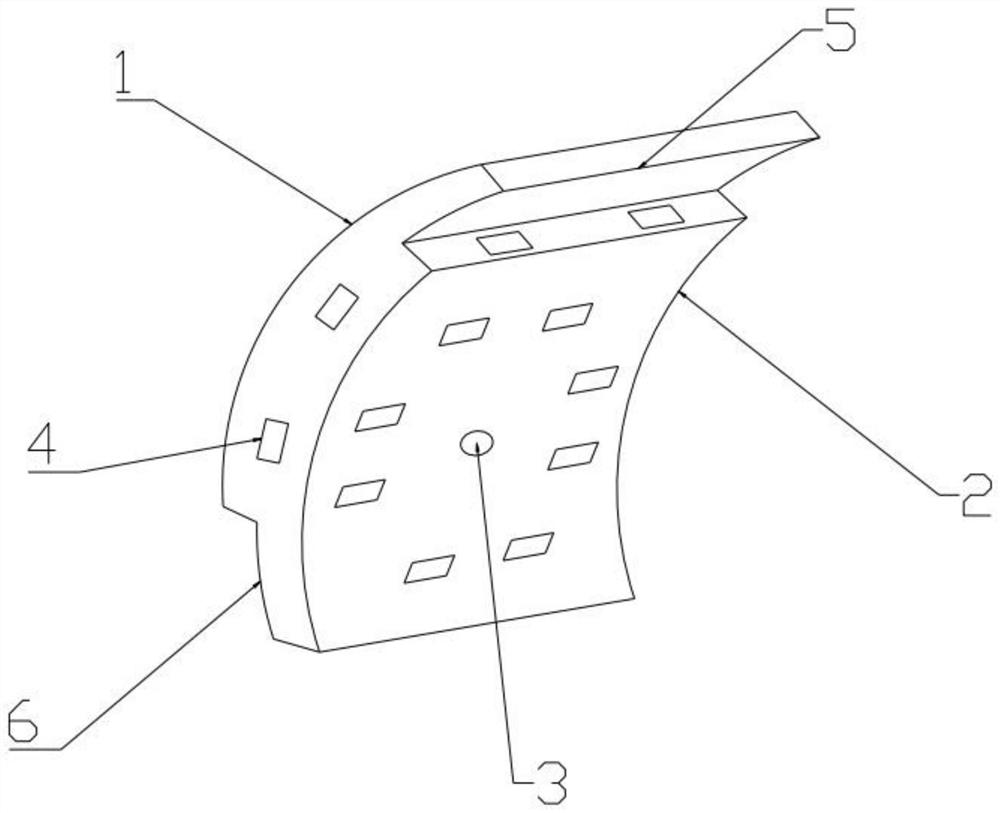
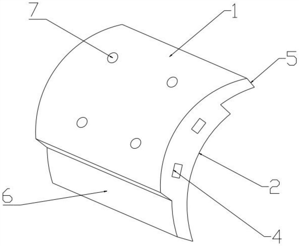
[0032] Specific implementation plan one: combine Figure 1 to Figure 4 As shown, the present invention provides a prefabricated subway shield segment, the shield segment is an arc-shaped body, one end of the shield segment is a first stepped structure 5, and the other end of the shield segment For the second stepped structure 6 matching the first stepped structure 5, the first stepped structure 5 for the shield segment is connected to the second stepped structure 6 of the adjacent shield segment, and the shield segment The inner arc surface 2 of the shield segment is provided with a first grouting hole 3, and the outer arc surface 1 of the shield segment is provided with at least three second grouting holes 7, and the first grouting hole 3 and the second injection hole The grout hole 7 forms a connecting pipe inside the shield segment, which is used for the secondary grouting process to allow the grout to quickly fill the gap between the shield segment and the soil body. Both ...

specific Embodiment approach 2

[0034] Specific implementation plan two: combine Figure 1 to Figure 4 As shown, the radian threshold of the shield segment is π / 8-π / 5, that is, the 10-16 ring shield segment structure is used for staggered annular splicing, which can be adjusted accordingly according to the construction environment. The other combinations and connections of this embodiment are the same as those of Embodiment 1.

specific Embodiment approach 3

[0035] Specific implementation plan three: combination Figure 1 to Figure 4 As shown, the arc length of the connecting part of the first stepped structure 5 and the second stepped structure 6 accounts for 1 / 3-1 / 2 of the arc length of the outer arc surface 1 of the shield segment. The setting of the arc length of the connecting part of the first stepped structure 5 and the second stepped structure 6 can ensure the stability of the connecting part and facilitate the installation of positioning bolts. The other combinations and connections of this embodiment are the same as those of Embodiment 1.

[0036] Specific implementation plan four: combination Figure 1 to Figure 4As shown, at least two bolt holes 4 are provided on both sides of the shield segment, and at least six bolt holes 4 are arranged on the inner arc surface 2 of the shield segment in a circular shape. The first stepped structure 5 At least two bolt holes 4 are provided on the end face of the joint with the seco...


PUM

PropertyMeasurementUnit
specific surface areaaaaaaaaaaa
particle sizeaaaaaaaaaa
thicknessaaaaaaaaaa

Abstract

The invention provides a prefabricated subway shield segment and a detection and installation method thereof, and belongs to the technical field of subway shield segments and installation methods thereof. The problems that a traditional shield segment is large in site construction pollution, the grouting speed of the shield segment is low, and the gap filling effect is poor are solved. A first step structure and a second step structure which are matched with each other are arranged at the two ends of the shield segment, first grouting holes are formed in the inner arc face, at least three second grouting holes are formed in the outer arc face, the first grouting holes and the second grouting holes form a communicating pipeline in the shield segment, bolt holes are formed in the two sides and the inner arc face of the shield segment, and bolt holes are formed in the end faces of the first step structure and the second step structure. Shield segments are prefabricated in a factory and then spliced in a staggered joint mode, primary grouting treatment is carried out, a three-dimensional laser scanner is adopted for scanning, and SBS modified asphalt is used for joint sealing treatment. The grouting hole channel is formed in each shield segment, the grouting speed is high, the three-dimensional laser scanner is used for detecting and caulking, and the waterproofness is effectively improved.

Description

technical field [0001] The invention relates to the technical field of a subway shield segment and an installation method thereof, in particular to a prefabricated subway shield segment and a detection and installation method thereof. Background technique [0002] With the continuous development of the scale of urban construction, major cities in China have successively begun to develop subways and urban underground spaces and transform urban water supply and drainage systems. The shield method construction technology is a construction method widely used in underground tunnel construction. The installation of internal equipment and pipelines is an important construction link to realize the function of shield tunneling. [0003] The shield segment is the main assembly component of shield construction and the innermost barrier of the tunnel, which bears the role of resisting soil pressure, groundwater pressure and some special loads. The shield segment is the permanent lining...

Claims


Application Information

Patent Timeline
Patent Type & Authority Applications(China)
IPC IPC(8): E21D11/08E21D11/10G01B11/24G01N21/88
CPCE21D11/08E21D11/083E21D11/105G01B11/24G01N21/8851G01N2021/8887
Inventor 肖妙武常东辉程荣君朱火焰琚超龚柯房桢
Owner CCCC SECOND HARBOR ENG
Why Eureka
Try Eureka