Stepless variable internal combustion engine air inflow system

A technology of air intake system and internal combustion engine, which is applied in the direction of charging system, intake muffler, combustion air/combustion-air treatment, etc., can solve the problems of low practicality and reliability, achieve optimal charging efficiency, optimize the speed range, The effect of broad resonant frequency

Pending Publication Date: 2019-01-25
NANJING INST OF TECH
View PDF33 Cites 0 Cited by
  • Summary
  • Abstract
  • Description
  • Claims
  • Application Information

AI Technical Summary

Problems solved by technology

The traditional internal combustion engine has a fixed length and diameter intake manifold and a fixed volume resonance box, so the resonant speed of this type of engine is fixed, and the charging efficiency of the engine can only reach the highest at a certain speed
However, the existing widely used staged variable intake manifold length engines can only change the length of the engine intake manifold at a fixed speed and change the inherent resonance frequency. Although it has been improved, it is practical and reliable. lower
There are also manufacturers that make continuously variable intake manifolds or resonance boxes, but they can only change the parameters of one part of the intake system. Under extreme conditions, the intake system needs to make large changes to make the system reach or approach resonance. gas request

Method used


Image

  • Stepless variable internal combustion engine air inflow system
  • Stepless variable internal combustion engine air inflow system
  • Stepless variable internal combustion engine air inflow system

Examples


Embodiment Construction

[0029] The present invention will be further described below in conjunction with specific embodiments.

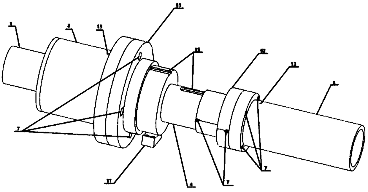
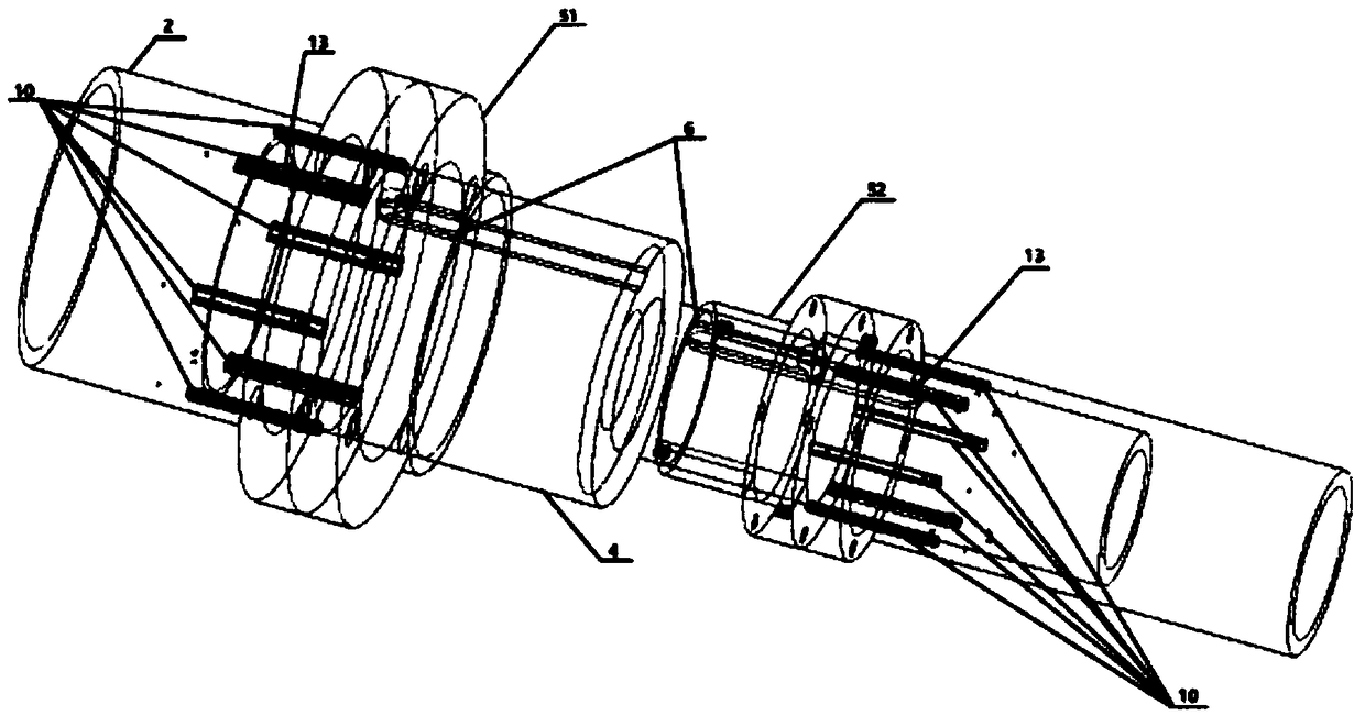
[0030] An infinitely variable intake system for an internal combustion engine, comprising an intake manifold 1, a resonance box shell 2, an intake manifold outer pipe 3, a connecting pipe 4, a flange, a feather key 6, bolts, washers, and sealing gaskets , Slider guide rail device, screw slider 11 and drive device. The driving device includes a servo motor 16 and a reduction gear set controlled by the ECU. The driving device and the screw slider device 11 are fixed to the outside of the resonance box shell 2 and the outer pipe 3 of the intake manifold through a bracket. There are two kinds of flanges, which are respectively used for the fixed connection between the connecting pipe 4 and the resonance box shell 2 and the outer pipe 3 of the intake manifold.

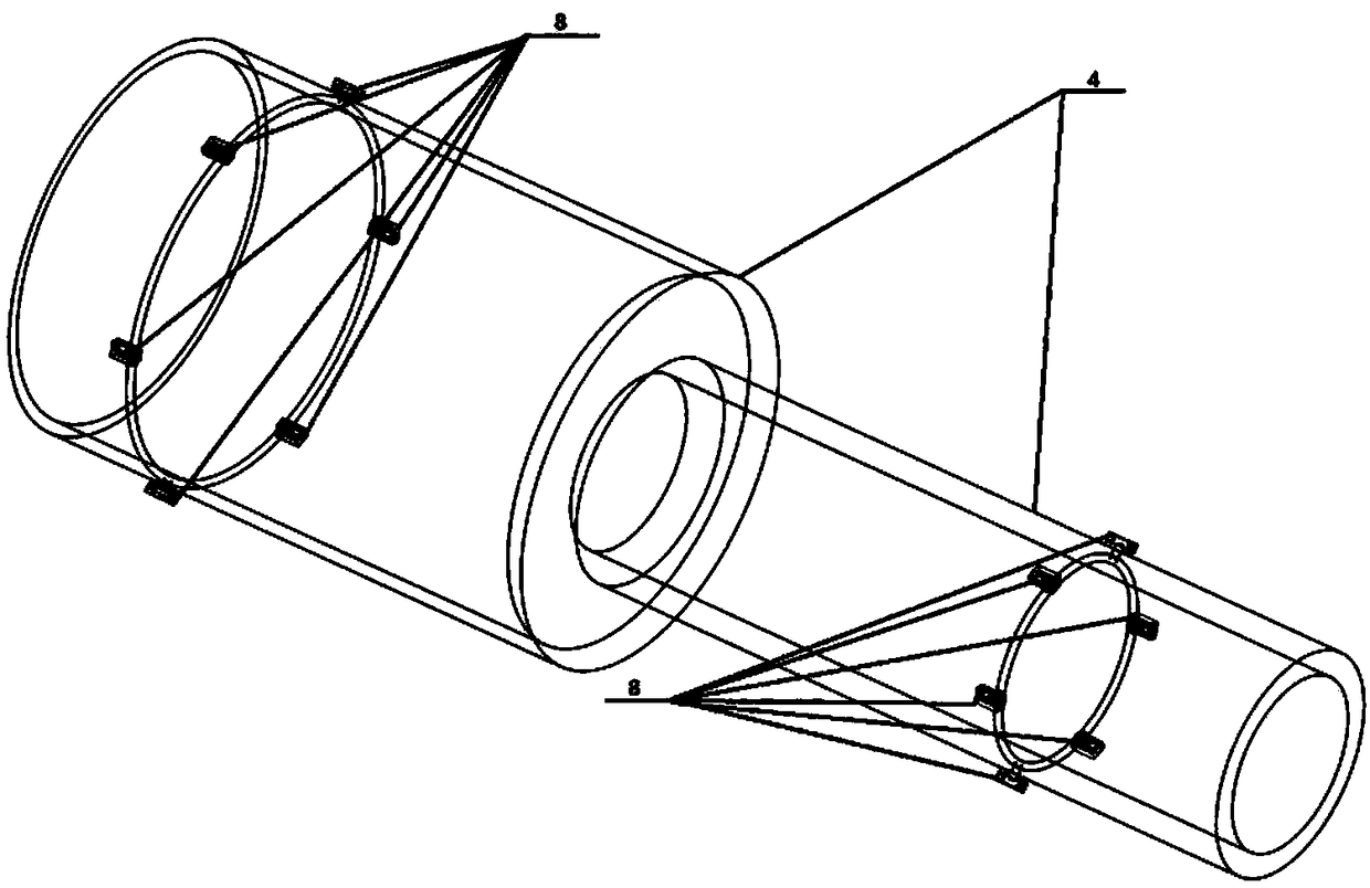
[0031] A slider 8 is installed at the front and rear of the connecting pipe 4 to guide the axial movement of the con...


PUM


Abstract

The invention relates to a stepless variable internal combustion engine air inflow system. The stepless variable internal combustion engine air inflow system comprises an air inflow main pipe, a resonance box shell, an air inflow divided manifold outer pipe, a connecting pipe, flange plates, a sliding block guide rail device, a lead screw sliding block device and a drive device. The drive device and the lead screw sliding block device are fixed outside the resonance box shell and the air inflow divided manifold outer pipe through supports. The drive device comprises a servo motor and a reduction gear set. Sliding blocks are mounted on the front portion and the rear portion of the connecting pipe and guide axial movement of the connecting pipe, and the distances between the sliding blocks and the shaft end face are determined through the size change of a resonance box and the mounting positions of guide rails. During assembly, firstly, the sliding blocks of the connecting pipe are positioned in the guide rails of the resonance box shell and the air inflow divided manifold outer pipe, and the connecting pipe, the resonance box shell and the air inflow divided manifold outer pipe arefixed respectively through the flange plates. The optimization effect is obvious, and the power performance and the oil consumption level of an engine are both improved.

Description

technical field [0001] The invention relates to the technical field of engines, in particular to a steplessly variable intake system for an internal combustion engine. Background technique [0002] Since the intake process of the engine is periodic and intermittent, if an intake system composed of an intake manifold of a certain length and diameter and a resonance box of a certain volume is used, the natural frequency of the whole system and the periodicity of the valve are coordinated, that is, At a certain speed, the intake wave peak moves to the vicinity of the valve when the intake valve is opened, and a large pressure wave is generated before the intake valve closes, which increases the charge coefficient of the engine, thereby increasing the power and torque of the engine. Then the intake mode is called resonance intake. The traditional internal combustion engine has an intake manifold with a fixed length and diameter and a resonance box with a fixed volume, so the re...

Claims


Application Information

Patent Timeline
Patent Type & Authority Applications(China)
IPC IPC(8): F02M35/104F02M35/12
CPCF02M35/104F02M35/1255
Inventor 韦思航张袁元吕喆关瑞元
Owner NANJING INST OF TECH
Why Eureka
Try Eureka