Supercharge Your Innovation With Domain-Expert AI Agents!

Heat Exchanger

A technology of heat exchangers and heat exchanger fins, applied in heat exchanger sealing devices, heat transfer modification, heat exchange equipment, etc., can solve the problems of easy corrosion of heat exchangers, reduce the corrosion resistance of heat exchangers, etc., and achieve Effect of improving corrosion resistance

Active Publication Date: 2021-09-28
ZHEJIANG DUNAN THERMAL SCI & TECH
View PDF10 Cites 0 Cited by
  • Summary
  • Abstract
  • Description
  • Claims
  • Application Information

AI Technical Summary

Problems solved by technology

[0004] The purpose of the present invention is to provide a heat exchanger to solve the problem that the bending position of the heat exchanger in the prior art is easy to corrode and reduce the overall corrosion resistance of the heat exchanger

Method used


Image

  • Heat Exchanger
  • Heat Exchanger
  • Heat Exchanger

Examples


Embodiment Construction

[0025] The embodiments of the present invention will be described in detail below, but the present invention can be implemented in a variety of different ways of claims;

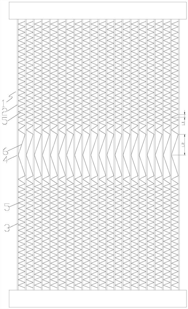
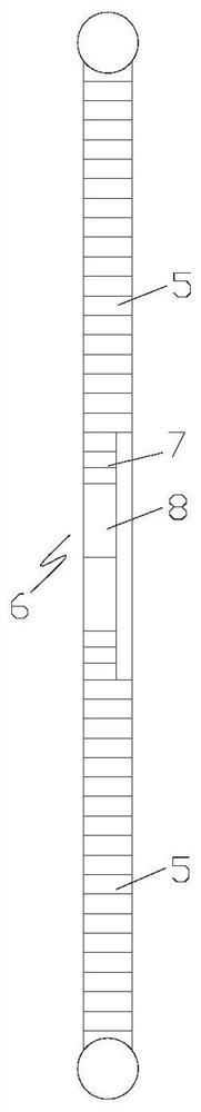
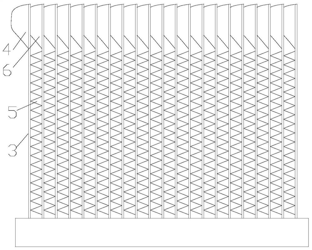
[0026] Please refer to Figure 1 to 17 As shown, according to an embodiment of the present invention, the heat exchanger includes a plurality of flat tube 1 arranged in a width direction, and the flat tube 1 includes a first straight tube section 2 and a second straight pipe section 3 located at both ends, and connected in the first The bending section 4 between the tube segment 2 and the second straight pipe section 3, between the adjacent first straight pipe segments 2 and between the adjacent second straight pipes 3, respectively, respectively, the first heat exchange sheet 5, bend The tube section 4 is provided with a second heat exchange sheet 6 having a low potential than the flat tube 1.

[0027] The heat exchanger of the present invention is provided at the position of the casing section 4 of the flat tub...


PUM


Abstract

Connection plate The present invention provides a heat exchanger. The heat exchanger includes a plurality of flat tubes (1) arranged at intervals along the width direction, the flat tubes (1) include a first straight tube section (2) and a second straight tube section (3) at both ends, and are connected to the first The bent pipe section (4) between the straight pipe section (2) and the second straight pipe section (3) is respectively arranged between adjacent first straight pipe sections (2) and adjacent second straight pipe sections (3) There is a first heat exchange fin (5), and a second heat exchange fin (6) with a potential lower than that of the flat tube (1) is arranged at the bend pipe section (4). According to the heat exchanger of the present invention, the problem in the prior art that the bending position of the heat exchanger is easily corroded and the overall corrosion resistance of the heat exchanger can be solved can be solved.

Description

Technical field [0001] The present invention relates to the field of air conditioning, and more particularly to a heat exchanger. Background technique [0002] A heat exchanger is disclosed in the Chinese patent application of the disclosure of CN1107221A, which includes a plurality of flat tubes disposed side by side by side by side by side in a thickness direction, and ends of the end and tubes in the tube in a thickness direction. A pair of hollow split pipes, the tube having a curved portion that is bent in the width direction of the tube at its longitudinal position, and the curved portion is also reversed to the regulated angle with respect to the straight tube portion on both sides. The bending portion and the heat sink disposed between adjacent straight tubes. [0003] This structure solves the problem of the double-row reducing instrument, but because the flat tube is turned around 90 degrees, the torsion area will have a transition section, which causes a larger gap to ...

Claims


Application Information

Patent Timeline
Patent Type & Authority Patents(China)
IPC IPC(8): F28F11/02F28F13/08F28F19/00
CPCF28F11/02F28F13/08F28F19/002
Inventor 汪峰黄洪波朱利华
Owner ZHEJIANG DUNAN THERMAL SCI & TECH
Features
  • R&D
  • Intellectual Property
  • Life Sciences
  • Materials
  • Tech Scout
  • Unparalleled Data Quality
  • Higher Quality Content
  • 60% Fewer Hallucinations
Learn More