Lower limb external skeleton robot
A kind of exoskeleton robot and robot technology, which can be applied in the direction of equipment to help people walk, physical therapy, etc., and can solve the problems of low energy utilization efficiency and heavy mechanism weight
- Summary
- Abstract
- Description
- Claims
- Application Information
AI Technical Summary
Problems solved by technology
Method used
Image
Examples
Embodiment 1
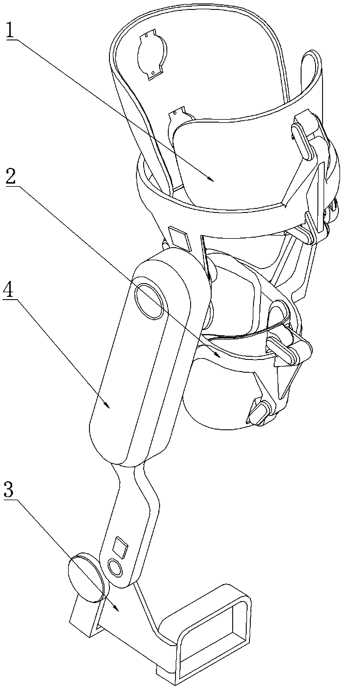
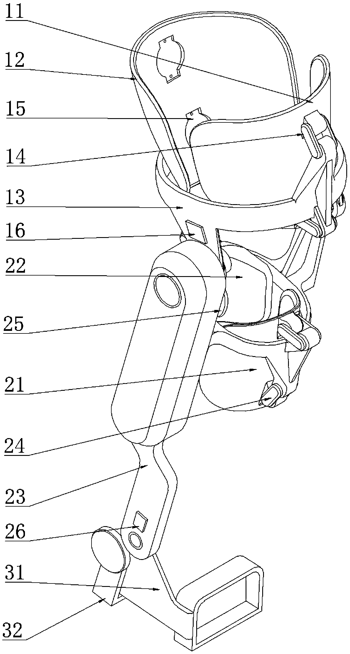
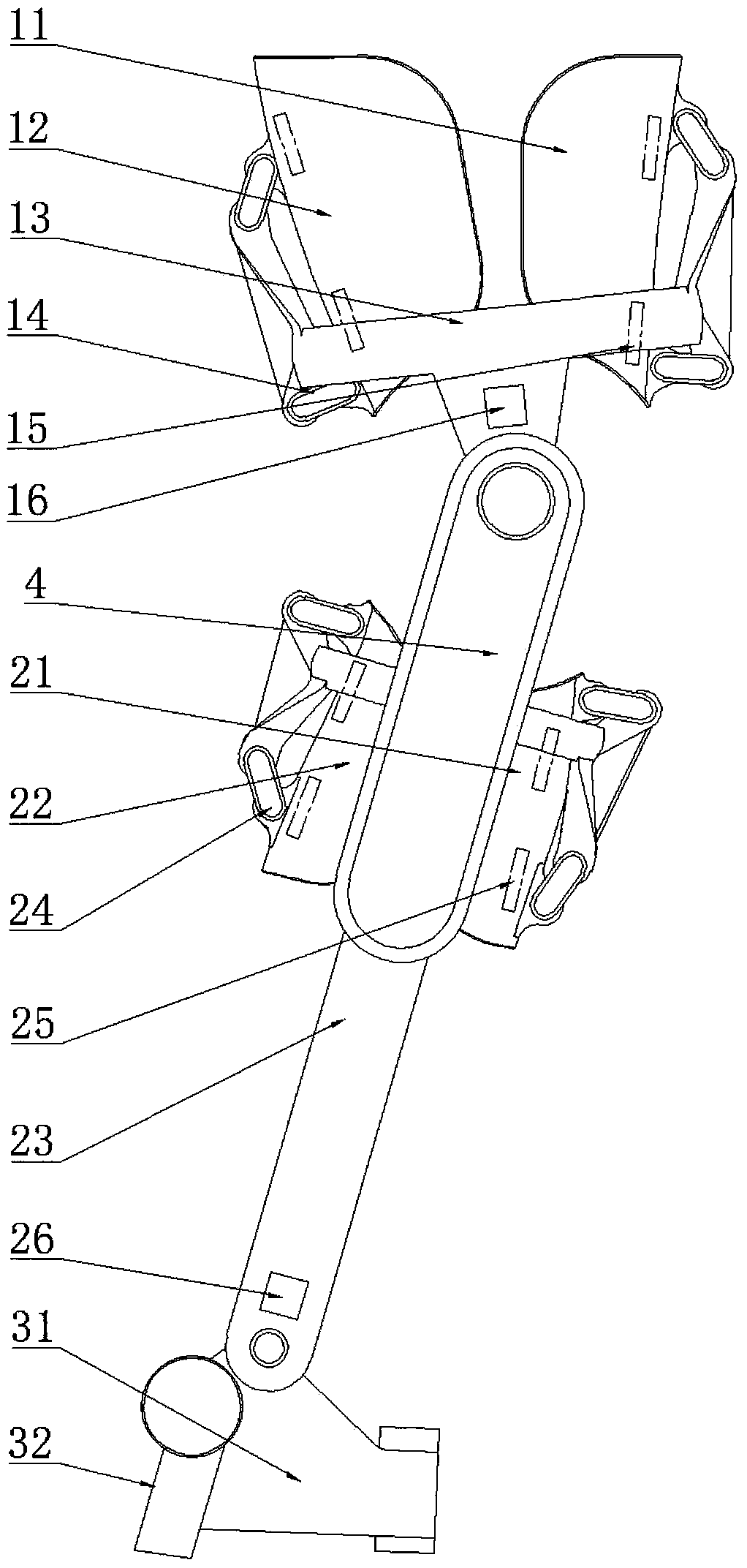
[0117] Such as Figure 1-Figure 3 As shown, the skeletal robot of this embodiment includes a thigh support part 1, a shin support part 2, a foot support part 3 and a power chamber 4;
[0118] The thigh support part 1 and the shin support part 2 are connected by a set of joints, hereinafter referred to as "exoskeleton knee joint"; the tibia support part 2 and the foot support part 3 are connected by a set of joints, hereinafter referred to as "exoskeleton knee joint" Exoskeleton ankle joint "; the power chamber 4 is fixed on the side of the shin support part 2.
[0119] The thigh support part 1 includes a thigh front support plate 11, a thigh rear support plate 12, a thigh frame 13, a thigh gyroscope and an acceleration sensor 16, and four connecting rods 14 of the thigh. Sensor 15 four.
[0120] The main body of the stock frame 13 is ring-shaped, and the stock front side support plate 11 and the stock rear side support plate 12 are located on the front and rear sides of the ...
Embodiment 2
[0134] The embodiment of the present invention provides a control method for the exoskeleton robot described in Embodiment 1. The control method includes a motion intention predictor, an energy collection estimator, an energy recovery trigger, a finite-time convergent disturbance observer and a non-singular terminal sliding mode controller, and the specific steps are as follows.
[0135] In the first step, the embedded single-chip microcomputer uses the thigh pressure sensor 15 to collect the contact force F between the thigh and the front support plate 11 and the rear support plate 12 respectively. g1 , F g2 , F g3 , F g4 Utilize the shank pressure sensor 25 to collect the contact force F between the shank and the front side support plate 21 of the tibia and the rear side support plate 22 of the tibia respectively j1 , F j2 , F j3 , F j4 ; Then, according to the following formulas (1)-(4), the expected angle signal q of the knee joint that reflects the trajectory of the...
PUM
 Abstract
Description
Claims
Application Information
 - R&D
- Intellectual Property
- Life Sciences
- Materials
- Tech Scout
- Unparalleled Data Quality
- Higher Quality Content
- 60% Fewer Hallucinations
Browse by: Latest US Patents, China's latest patents, Technical Efficacy Thesaurus, Application Domain, Technology Topic, Popular Technical Reports.
© 2025 PatSnap. All rights reserved.Legal|Privacy policy|Modern Slavery Act Transparency Statement|Sitemap|About US| Contact US: help@patsnap.com


